Eureka AIR delivers breakthrough ideas for toughest innovation challenges, trusted by R&D personnel around the world.

Sealing segment and sealing-segment arrangement

a sealing segment and sealing segment technology, applied in engine seals, leakage prevention, stators, etc., can solve the problems of lasting negative impact on the life limited relative movement of the two structural components with respect to one another, and costly sandwich construction, so as to enhance the sealing effect between adjacent sealing segments, and increase the elasticity of the sealing segment

Active Publication Date: 2015-11-10
MAN ENERGY SOLUTIONS SA
View PDF25 Cites 5 Cited by
  • Summary
  • Abstract
  • Description
  • Claims
  • Application Information

AI Technical Summary

Benefits of technology

[0004]It is an object of the present invention to provide a sealing segment that permits different relative movements between adjacent structural component parts and which has a long life, a sealing segment arrangement, and a flow machine with a sealing segment arrangement of this kind.
[0005]A sealing segment according to the invention for sealingly connecting two adjacent structural component parts which are movable relative to one another has two sealing bodies which are connected to one another by a web. The sealing bodies can be arranged in recesses of the structural component parts and, together with the latter, form a sliding bearing. The sealing segment is accordingly disposed in an articulated manner between the two structural component parts so that a swiveling movement and an axial movement of the two structural component parts relative to one another can be compensated. In so doing, the sealing segment is not warped or deformed so that it has a long life compared to the known solution. At the same time, a tight connection with respect to pressure and temperature is produced over the entire relative movement. Further, an offset between the structural component parts can be compensated without tension by the articulated construction of the sealing segments according to the invention.

Problems solved by technology

One of the disadvantages of this sealing segment is the costly sandwich construction.
It is further disadvantageous that this sealing segment only allows a rotational relative movement between the two structural component parts.
The maximum relative movement of the two structural component parts with respect to one another is limited by the shear strength of the sealing segment.
Therefore, with every relative movement the sealing segment is subjected to material fatigue which has a lasting negative impact on the life of the sealing segment.

Method used


Image

  • Sealing segment and sealing-segment arrangement
  • Sealing segment and sealing-segment arrangement
  • Sealing segment and sealing-segment arrangement

Examples


Embodiment Construction

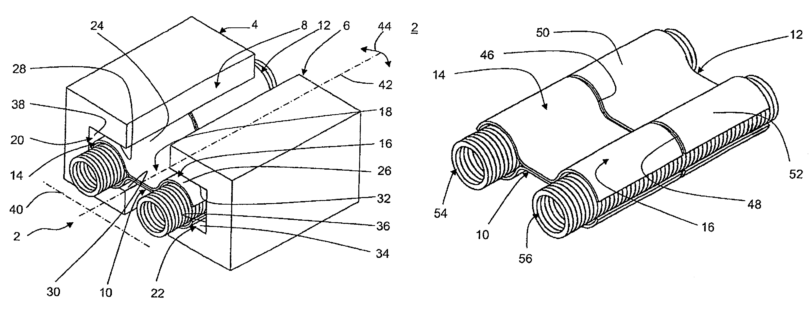
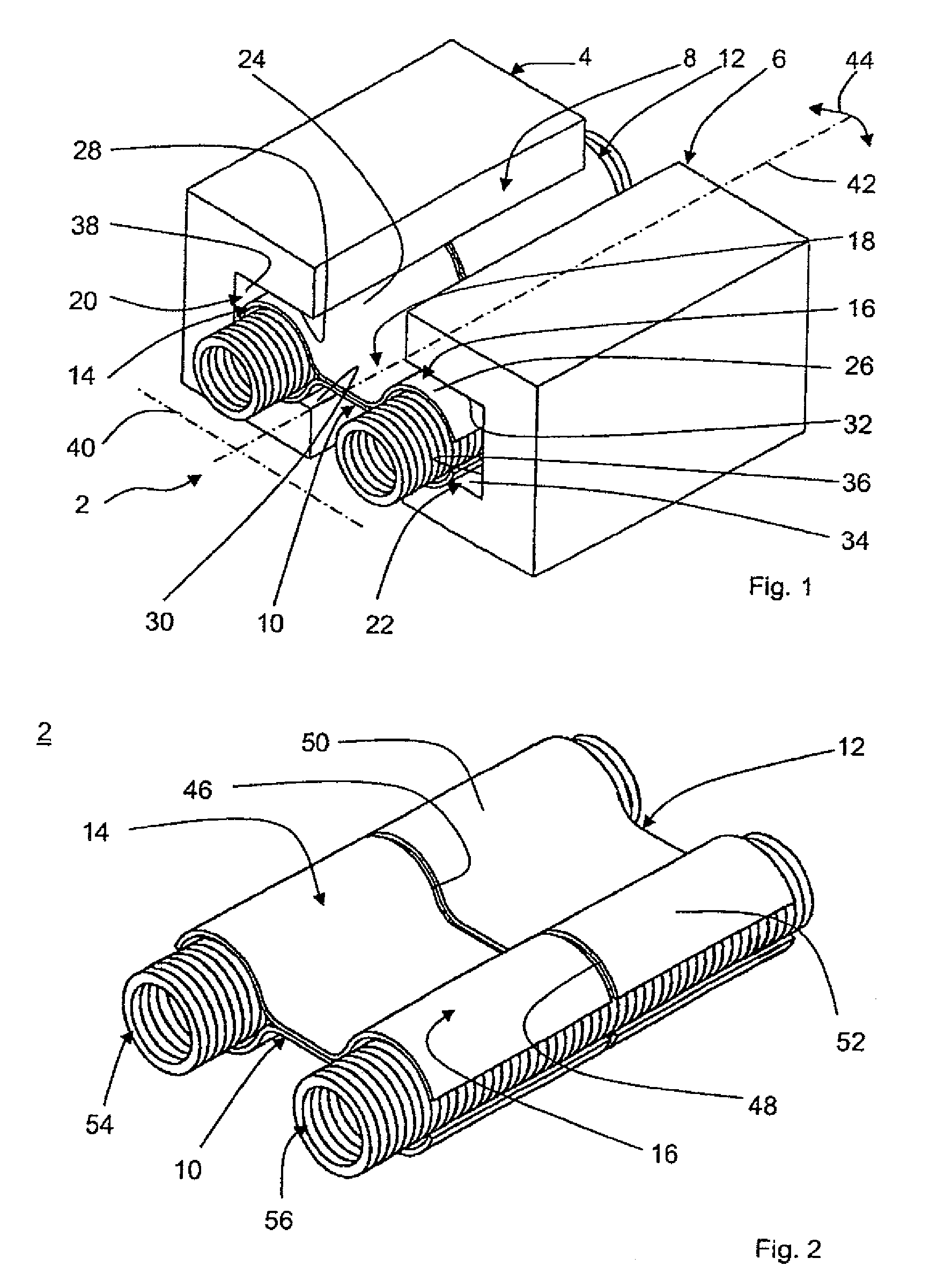
[0027]FIG. 1 shows a three-dimensional view of a sealing segment arrangement 2 according to the present invention for connecting two adjacent structural component parts 4, 6 so as to be sealed with respect to pressure and temperature. The structural component parts 4, 6 are shown in a highly simplified manner and are separated from one another by a gap 8. The sealing segment arrangement 2 comprises a plurality of metal sealing segments, two of which 10, 12 are shown by way of example.

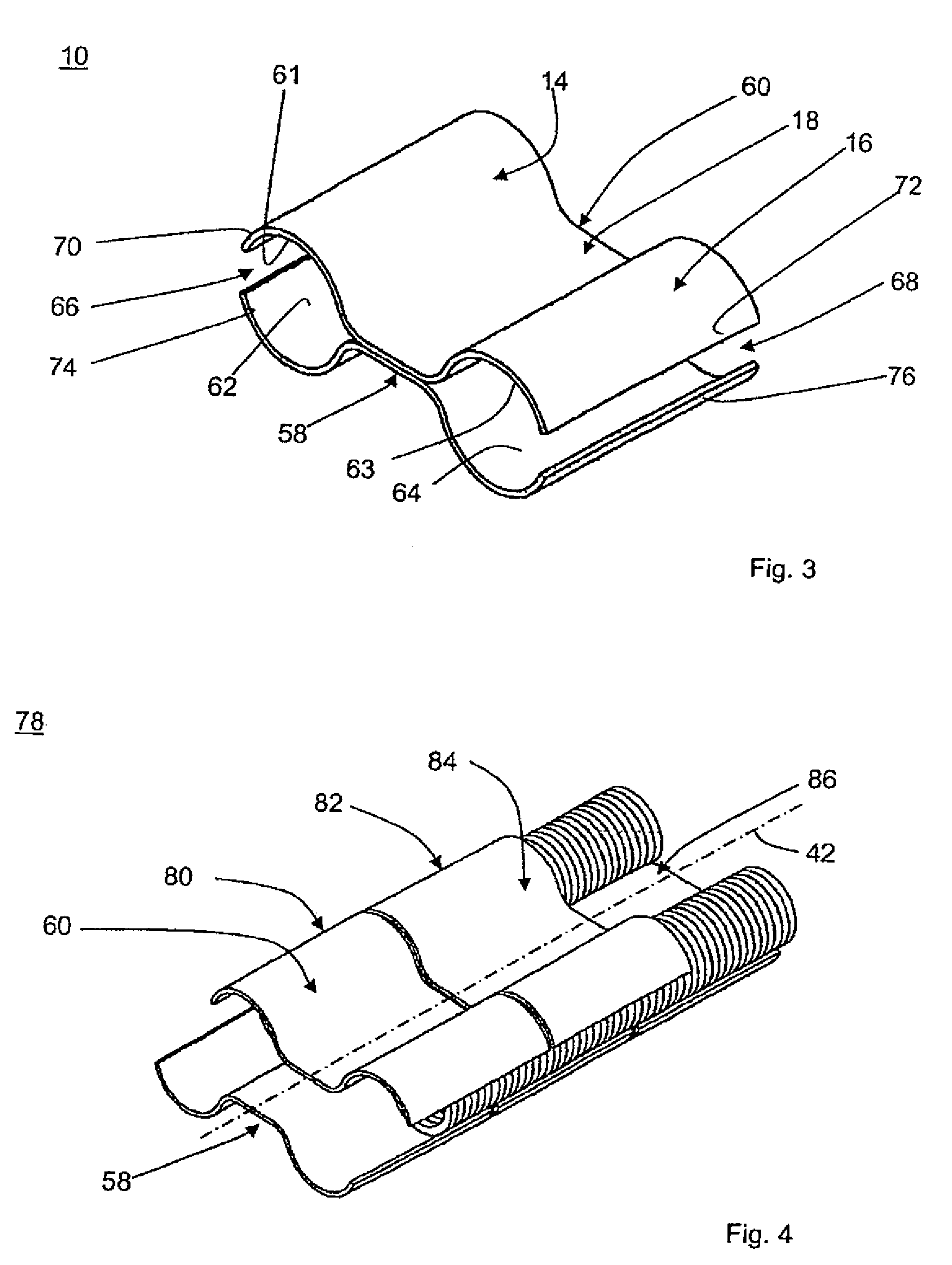
[0028]Each sealing segment 10, 12 has two axially parallel, cylindrical sealing bodies 14, 16 which are connected to one another in each instance by a web 18 which is constructed so as to have an extensive surface. The sealing bodies 14, 16 are radially springing and are partially enclosed in a U-shaped, rectangular longitudinal groove 20, 22 of the structural component parts with inner groove surfaces 28, 30 and 32, 34, respectively, extending parallel to one another in pairs. The sealing bodies 14, 16...


PUM


Abstract

A sealing segment for sealingly connecting two structural components parts which are movable relative to one another, with two sealing bodies which are connected to one another by a web and which can be arranged in recesses of the structural component parts in an articulated manner, and a sealing segment arrangement with a plurality of sealing segments of this type, and a flow machine with a sealing segment arrangement of this type.

Description

PRIORITY CLAIM[0001]This is a U.S. national stage of application No. PCT / EP2008 / 009257, filed on Nov. 3, 2008. Priority is claimed on the following application: Country: Germany, Application No.: 10 2007 062 681.0, Filed: Dec. 24, 2007, the content of which is / are incorporated here by reference.FIELD OF THE INVENTION[0002]The present invention is directed to a sealing segment according to claim 1 for sealingly connecting two structural components parts which are movable relative to one another, a sealing segment arrangement, and a flow machine with a sealing segment arrangement of this type.BACKGROUND OF THE INVENTION[0003]Sealing segments for sealingly connecting adjacent structural component parts are known per se. A sealing segment allowing a relative movement of adjacent structural component parts with respect to one another is disclosed, for example, in DE 2453645. This sealing segment comprises a plurality of metal rings and plastic rings in a sandwich-type construction and sh...

Claims


Application Information

Patent Timeline
Patent Type & Authority Patents(United States)
IPC IPC(8): F16J15/08F01D9/02F01D11/00
CPCF16J15/0893F01D9/023F01D11/005F05D2230/642F05D2240/11
Inventor ASCHENBRUCK, EMILBLASWICH, MICHAELEL MASALME, JAMANREISS, FRANK
Owner MAN ENERGY SOLUTIONS SA
Why Eureka
Eureka Blog
Learn More