Supercharge Your Innovation With Domain-Expert AI Agents!

Composite IC card

a technology ic cards, applied in the field of composite ic cards, can solve the problems of disconnection and deformation of the coil, increase in demand recently, etc., and achieve the effect of reducing defectiveness

Active Publication Date: 2015-11-10
TOPPAN PRINTING CO LTD
View PDF12 Cites 1 Cited by
  • Summary
  • Abstract
  • Description
  • Claims
  • Application Information

AI Technical Summary

Benefits of technology

The present invention aims to minimize connection defects such as disconnection and deformation in the coil used to connect an IC module with an electrical device.

Problems solved by technology

In the latter composite IC card, it is unnecessary to physically connect the IC module and the antenna coil with wiring and defects such as a loose connection are unlikely to be caused, which leads to its increased demand recently.
When forming the recess in the card base, depending on the accuracy of the processing machine and the position of the coil used to make an electrical connection with the IC module, it is possible to cause disconnection and deformation of the coil.

Method used


Image

  • Composite IC card
  • Composite IC card
  • Composite IC card

Examples


examples

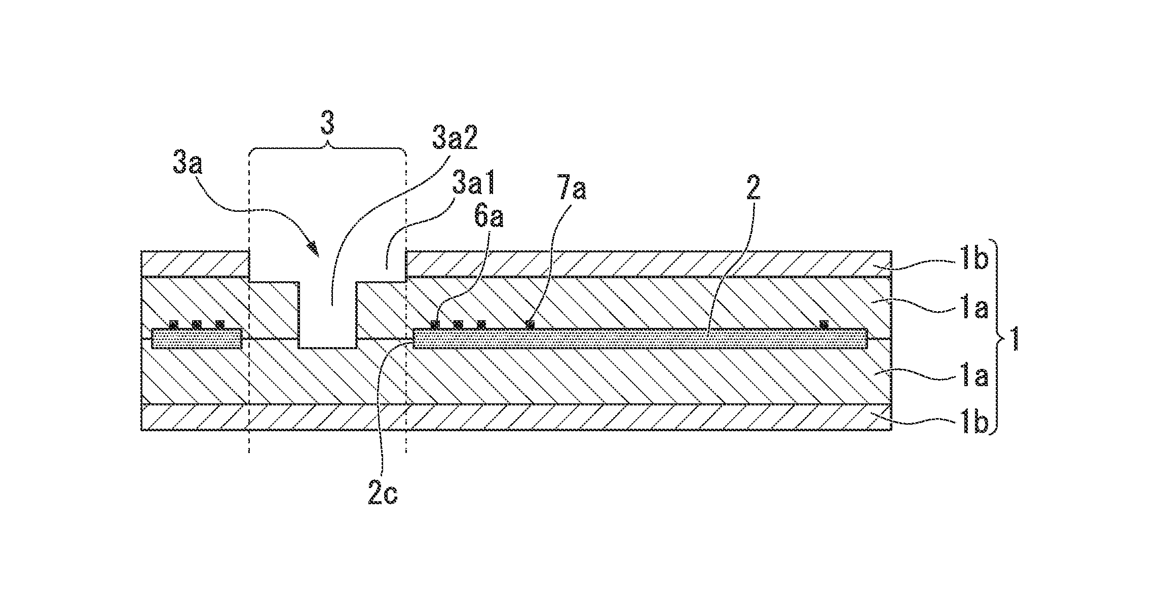
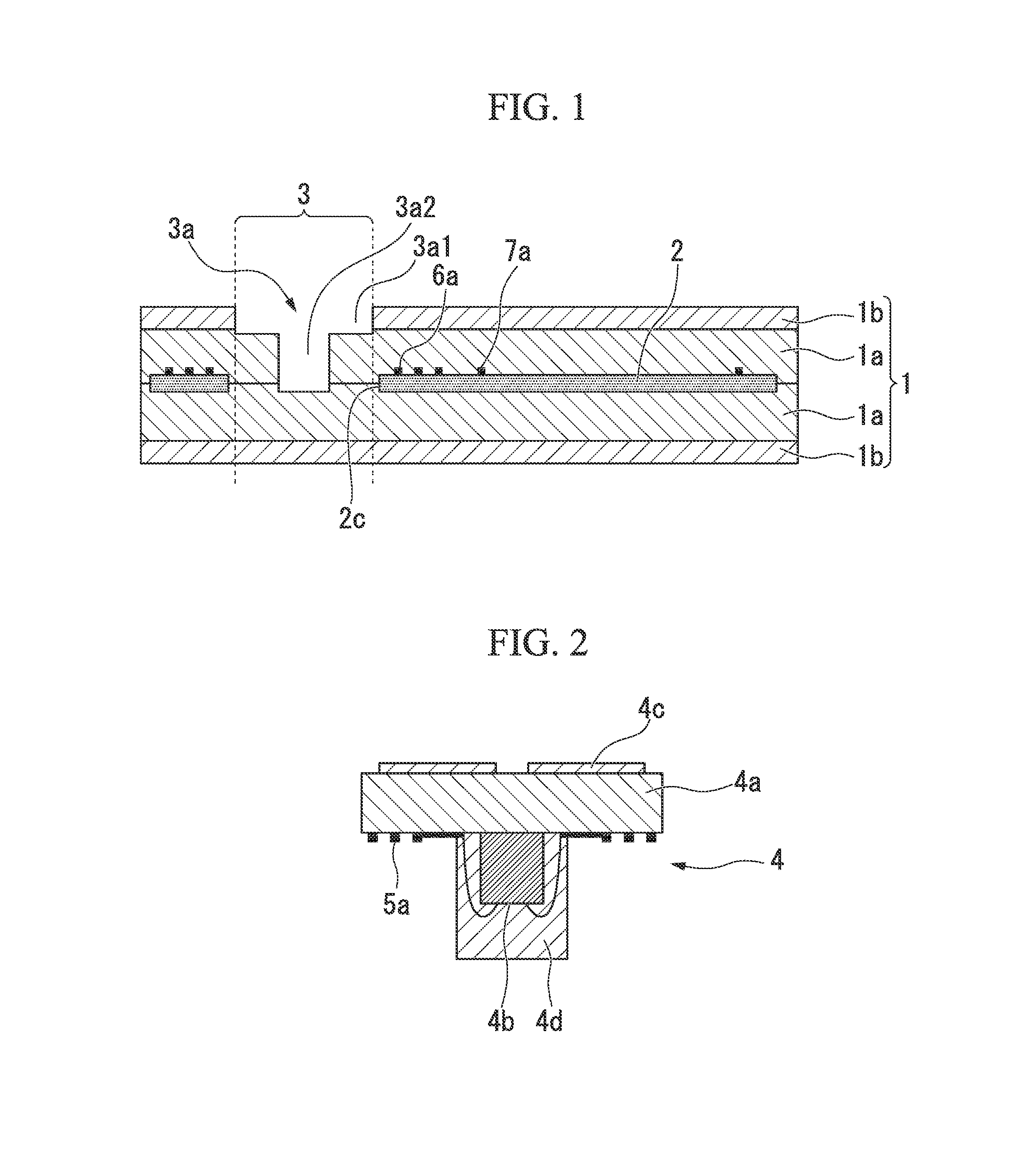
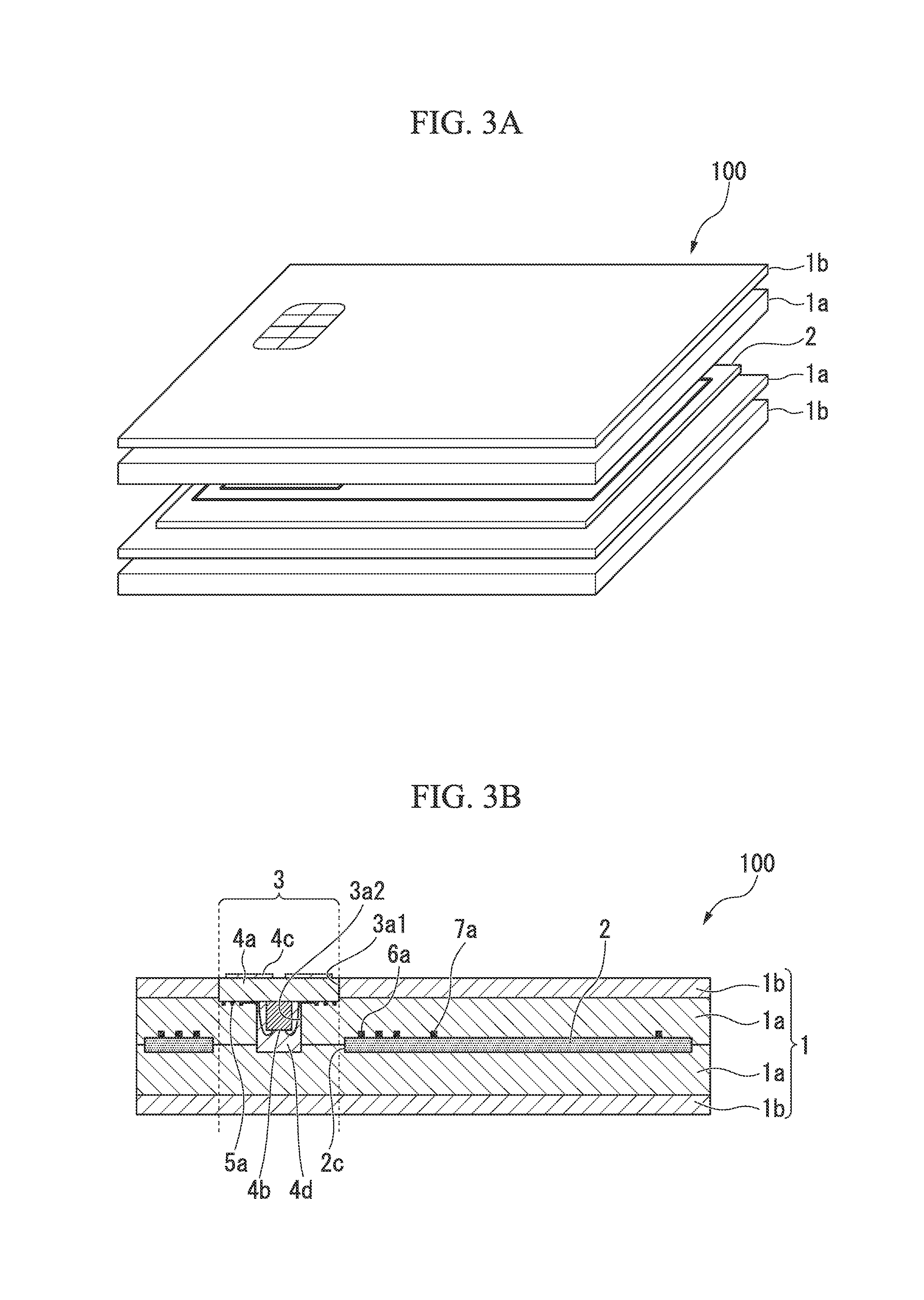
[0084]As the base, polyethylene terephthalate with a thickness of 80 μm provided with an aluminum thin film formed on both sides thereof was used. The second coupling coil 6a, the antenna coil 7a, and part of the capacitive element 8 were formed on one face of the base by etching, and the remaining part of the capacitive element 8 and a jumper line were formed on the other face of the base by etching to obtain the antenna sheet 2. The second coupling coil 6a and the antenna coil 7a were formed so as to make their line width be 1 mm. The second coupling coil region 6 were arranged outside the antenna coil region 7. The second coupling coil 6a was formed so as to make the number of turns be three turns, and the antenna coil 7a was formed so as to make the number of turns be one turn. In addition, the second coupling coil 6a was arranged such that the innermost turn of the second coupling coil region 6 was arranged outside the recess region of the card base. Further, the second couplin...


PUM


Abstract

Provided is a composite IC card including: a card base having a recess; an antenna sheet arranged inside the card base; an IC module arranged in the recess of the card base. The IC module includes an IC chip having a module substrate provided with an external terminal, and a first coupling coil. The antenna sheet includes an antenna coil configured to perform reception of electric power and transmission and reception of signals with an external reader, and a second coupling coil connected to the antenna coil. The first coupling coil and the second coupling coil are arranged so as to be capable of achieving close coupling therebetween and configured to couple the IC module with the antenna sheet in a non-contact manner by trans coupling. The second coupling coil of the antenna sheet is arranged outside a region in which the recess of the card base is formed.

Description

CROSS REFERENCE TO RELATED APPLICATIONS[0001]This application is a continuation application based on a PCT Patent Application No. PCT / JP2012 / 079992, filed Nov. 19, 2012, whose priority is claimed on Japanese Patent Application No. 2011-251437, filed Nov. 17, 2011, the entire content of which are hereby incorporated by reference.BACKGROUND OF THE INVENTION[0002]1. Field of the Invention[0003]The present invention relates to a composite IC card which is operable in both: a contact mode used to perform, for example, reception of electric power from an electric power supply and transmission and reception of signals via electric contacts; and a non-contact mode used to perform, for example, reception of electric power from an electric power supply and transmission and reception of signals by electromagnetic coupling in a non-contact manner without electric contacts in the IC card, and method of manufacturing the same.[0004]2. Description of the Related Art[0005]As an IC card having a bui...

Claims


Application Information

Patent Timeline
Patent Type & Authority Patents(United States)
IPC IPC(8): G06K19/06H01Q1/22H01Q1/40H01Q7/00G06K19/077
CPCG06K19/07783G06K19/07769G06K19/07794H01Q1/2225H01Q1/40H01Q7/00
Inventor NIHEI, HIROSHIGETSUKADA, TETSUYA
Owner TOPPAN PRINTING CO LTD
Features
  • R&D
  • Intellectual Property
  • Life Sciences
  • Materials
  • Tech Scout
  • Unparalleled Data Quality
  • Higher Quality Content
  • 60% Fewer Hallucinations
Learn More