Supercharge Your Innovation With Domain-Expert AI Agents!

Battery module control system and battery module control method

a battery module and control system technology, applied in the direction of lead-acid accumulators, electric generators, transportation and packaging, etc., can solve the problems of inability to extract original capacity, risk of reverse current, dependence on the worst degradation level of batteries, etc., to ensure safe use of secondary battery modules in a safe usage range, simple and inexpensive system, the effect of ensuring the safe use of an arbitrary secondary battery modul

Active Publication Date: 2015-11-10
ENVISION AESC ENERGY DEVICES LTD
View PDF11 Cites 5 Cited by
  • Summary
  • Abstract
  • Description
  • Claims
  • Application Information

AI Technical Summary

Benefits of technology

Enables the safe reuse of secondary battery modules by controlling switch circuits based on calculated allowable voltage differences and charge-discharge rates, ensuring safe operation without the need for expensive storage sections or standardized battery information management.

Problems solved by technology

The reason is that, when the charge and discharge associated with a reverse current between batteries become large, the reverse current involves risks, such as heat generation.
However, even when the reverse current prevention function is provided, large variations in capacity between batteries could lead to dependence on a battery having the worst degradation level (or a small capacity).
Therefore, it tends to be impossible to extract the original capacity.
Therefore, the problem is that the configuration required to reuse the secondary battery module becomes extremely complicated and expensive.
Therefore, the problem is that an arbitrary secondary battery module cannot be reused.

Method used


Image

  • Battery module control system and battery module control method
  • Battery module control system and battery module control method
  • Battery module control system and battery module control method

Examples


Embodiment Construction

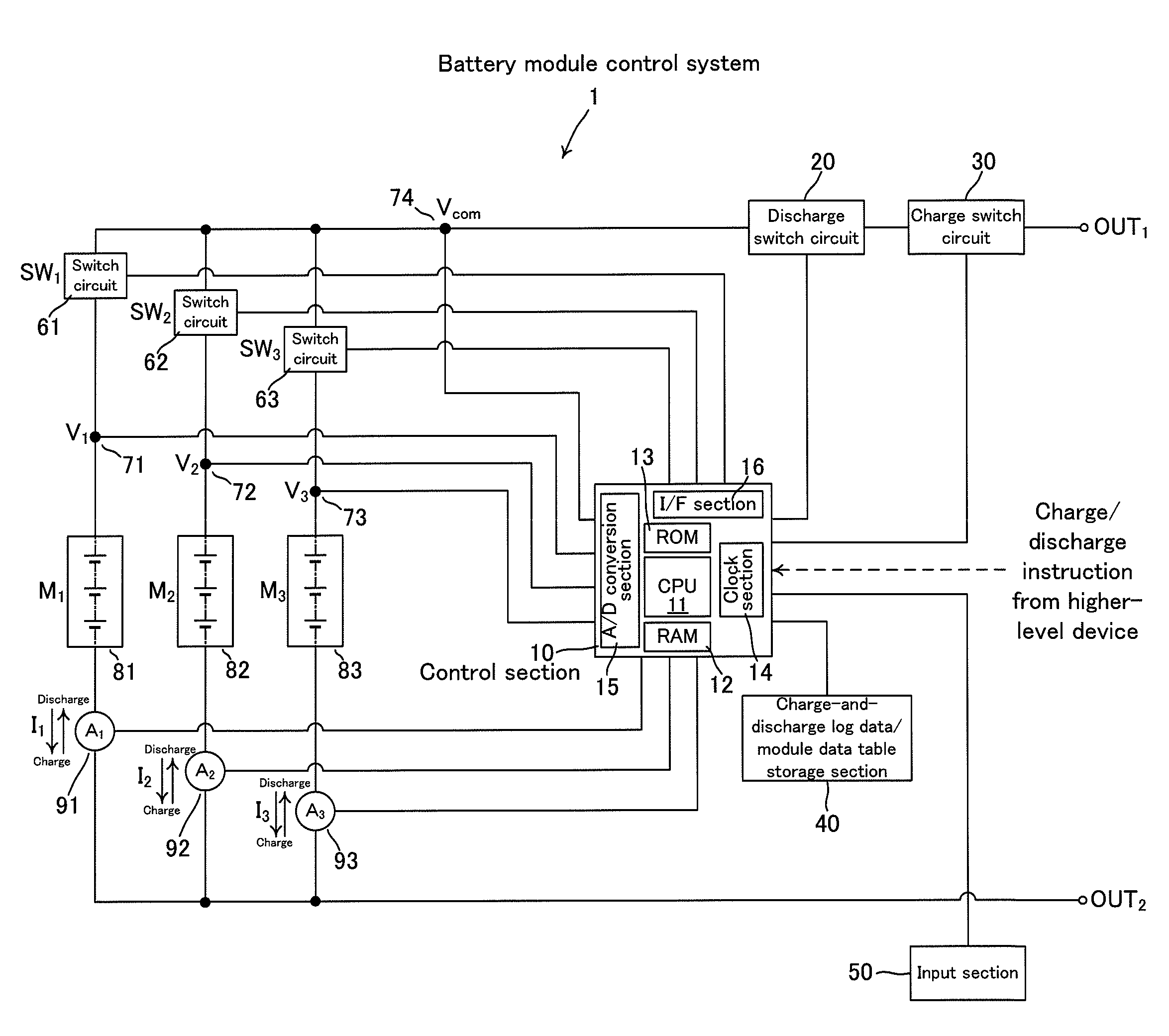
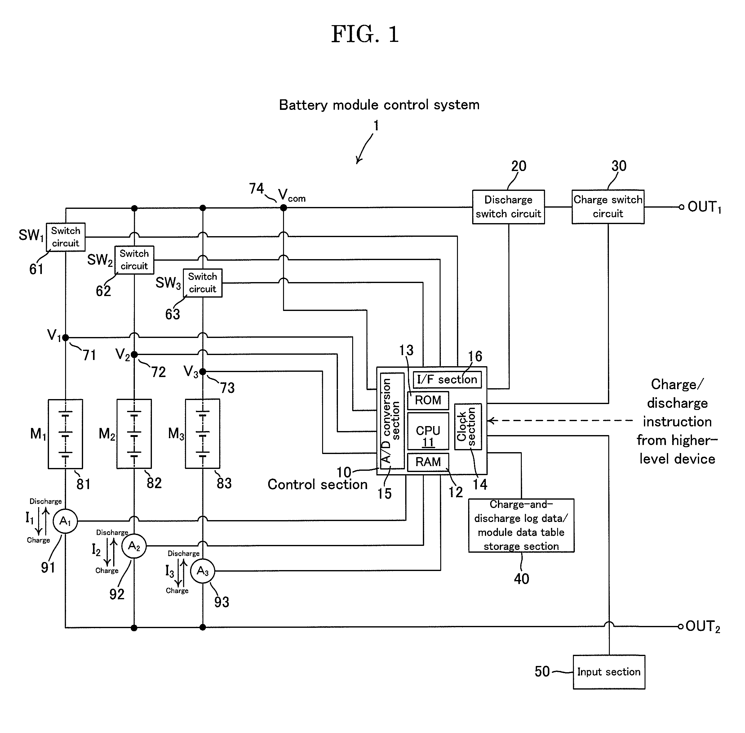
[0023]Hereinafter, an embodiment of the present invention will be described with reference to the accompanying drawings. FIG. 1 is a schematic diagram showing the circuit configuration of a battery module control system according to an embodiment of the present invention. FIG. 1 denotes a battery module control system 1, a control section 10, a CPU 11, a RAM 12, a ROM 13, a clock section 14, an A / D conversion section 15, an interface section 16, a discharge switch circuit 20, a charge switch circuit 30, a charge-and-discharge log data / module data table storage section 40, an input section 50, switch circuits 61, 62 and 63, voltage detection terminals 71, 72, 73 and 74, battery modules 81, 82 and 83, and current detection sections 91, 92 and 93.

[0024]The battery module control system 1 is a system that charges battery modules M1, M2 and M3, discharges the modules, or stops the charging or discharging in response to charge instructions / discharge instructions or charge stopping instruc...


PUM

PropertyMeasurementUnit
chargeaaaaaaaaaa
impedanceaaaaaaaaaa
charge-and-discharge rateaaaaaaaaaa

Abstract

In order to provide a battery module control system able to reuse an arbitrary secondary battery module through a simple, inexpensive system, the present invention includes: a plurality of battery modules that are connected to each other in parallel; switch circuits that are provided on charge and discharge routes of a plurality of the battery modules; an average impedance value calculation section (control section) that calculates average impedance values of a plurality of the battery modules; a maximum allowable charge-and-discharge rate input section (input section) that inputs maximum allowable charge-and-discharge rates of a plurality of the battery modules; an allowable voltage difference calculation section (control section) that calculates allowable voltage differences of a plurality of the battery modules on the basis of the average impedance values calculated by the average impedance value calculation section and the maximum allowable charge-and-discharge rates input by the maximum allowable charge-and-discharge rate input section; a common voltage detection section (control section) that detects a voltage of a common charge and discharge route of a plurality of the battery modules; and a plurality of voltage detection sections (control section) that detect voltages of a plurality of the battery modules, wherein, when a difference between the voltage detected by the common voltage detection section and the voltage detected by the voltage detection section corresponding to a predetermined battery module is greater than an allowable voltage difference of the predetermined battery module, a switch circuit provided on a charge and discharge route of the predetermined battery module is so controlled as to be turned OFF.

Description

CROSS REFERENCE TO RELATED APPLICATIONS[0001]This application is a National Stage of International Application No. PCT / JP2010 / 071174 filed on Nov. 26, 2010, which claims priority from Japanese Patent Application No. 2009-285816, filed on Dec. 17, 2009, the contents of all of which are incorporated herein by reference in their entirety.BACKGROUND OF THE INVENTION[0002]The present invention relates to a battery module control system and a battery module control method which are used to control a battery module including one or more battery cells.[0003]It is expected that, as awareness of environmental problems grows, vehicles driven by electric motors, such as electric vehicles (EV) and hybrid electric vehicles (HEV), systems that store electricity generated from sunlight, or the like will rapidly become popular. In such vehicles and electricity storage systems, lithium ion batteries, nickel-metal hydride batteries, lead batteries or any other secondary batteries are used. In the futu...

Claims


Application Information

Patent Timeline
Patent Type & Authority Patents(United States)
IPC IPC(8): H02J7/00H01M10/48H01M10/0525H01M10/06H01M10/34H02J7/02
CPCH01M10/482H02J7/0019H01M10/0525H01M10/06H01M10/345Y02T10/7011Y02T10/7016Y02T10/7055Y02W30/84Y02T10/70Y02E60/10
Inventor SUZUKI, SHIN
Owner ENVISION AESC ENERGY DEVICES LTD
Features
  • R&D
  • Intellectual Property
  • Life Sciences
  • Materials
  • Tech Scout
  • Unparalleled Data Quality
  • Higher Quality Content
  • 60% Fewer Hallucinations
Learn More