Adjustable parallax distance, wide field of view, stereoscopic imaging system

a stereoscopic imaging and parallax technology, applied in the field of wide field of view image recording devices, can solve problems such as creating potential obscuration between neighboring cameras, and achieve the effect of enhancing stereo performan

Active Publication Date: 2015-11-10
ACTALITY
View PDF40 Cites 68 Cited by
  • Summary
  • Abstract
  • Description
  • Claims
  • Application Information

AI Technical Summary

Benefits of technology

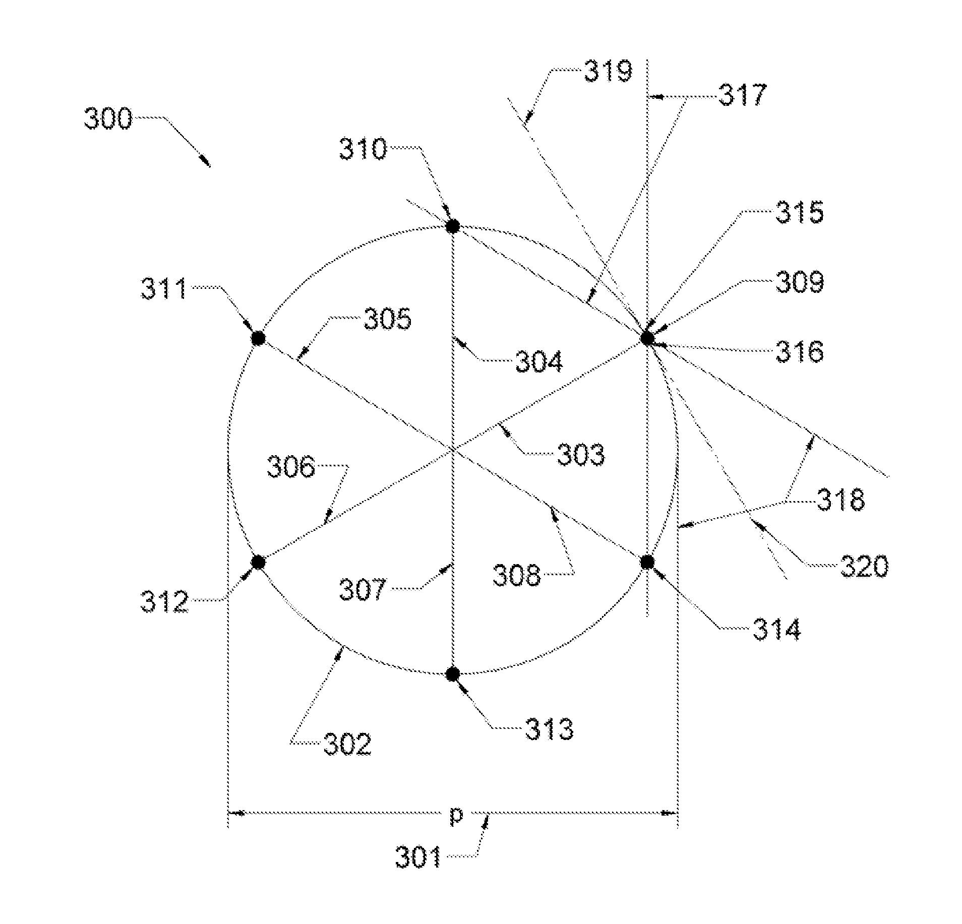
[0008]Embodiments of the present invention provide an improvement to the stereoscopic imaging system taught by Prechtl et. al. in U.S. Pat. Nos. 7,982,777 and 8,004,558. Various embodiments provide an imaging system where the operator is able to adjust the parallax distance for enhanced stereo performance. In addition, by coordinating the parallax distance with the optical settings of the camera, artificial 3D experiences can be created that give a user the perception of observing a scene from a distance different than that actually employed. Variable parallax distance embodiments are described that use adjustable mechanisms, static camera configurations or a combination of the two.
[0014]In a fifth embodiment, a method of encoding orientation data along with video data from a wide field of view camera system that is moving is described. The orientation data can be used to more smoothly access and view the video data.
[0023]In another related embodiment, each of the arms is pivotally coupled to a mounting pole that passes through the center of the circle and is disposed perpendicularly with respect to the horizontal plane, each of the arms having a link pivotally attached to a circumferential support that is slidably coupled to the mounting pole, so that motion of the circumferential support along the mounting pole adjusts the radius of the circle and therefore the parallax distance.
[0024]In yet another related embodiment, each of the arms is coupled to a sliding arm mechanism that allows the arms to move in substantially radial direction and that includes a rack and pinion, so that rotational motion of the pinion around its central axis adjusts the radius of the circle and therefore the parallax distance.

Problems solved by technology

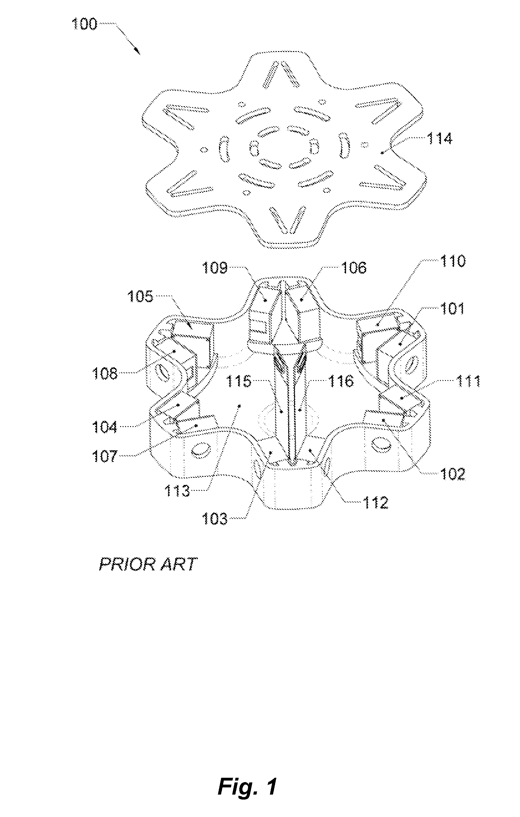
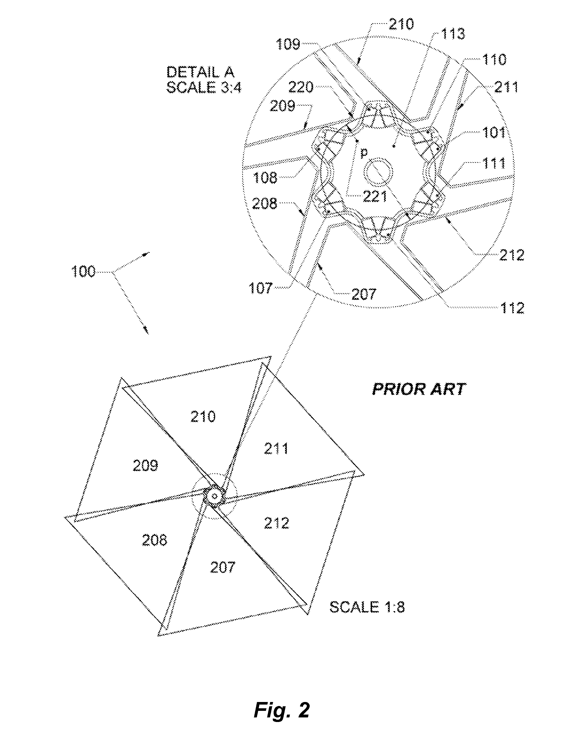
A differentiating characteristic of the above technology is that, due to the arrangement of cameras, it creates potential obscuration between neighboring cameras.

Method used


Image

  • Adjustable parallax distance, wide field of view, stereoscopic imaging system
  • Adjustable parallax distance, wide field of view, stereoscopic imaging system
  • Adjustable parallax distance, wide field of view, stereoscopic imaging system

Examples


embodiments-8 camera

Alternate Embodiments-8 Camera Design

[0167]FIG. 14 is a top view of a variable parallax distance, 8-arm camera system design, at a minimum parallax distance configuration in accordance with an embodiment the present invention. This figure is included to show that embodiments can be realized with an arbitrary number of arms. The operative philosophy of the design still governs. In the embodiment illustrated, there are 8 left-eye camera daughter boards 1401, 1402, 1403, 1404, 1405, 1406, 1407, and 1408 and 8 right-eye camera daughter boards 1409, 1410, 1411, 1412, 1413, 1414, 1415, and 1416. As with the six-camera design, the camera daughter boards are located near mount points at the ends of 8 arms through the use of telescoping components, rack transmissions and support brackets. For example, camera daughter boards 1401 and 1413 are mounted to support bracket 1417, which interfaces to the outer end of a telescoping arm mounted to the support housing 1426. The rack 1440 engages with ...


PUM


Abstract

An imaging system and methods for using an imaging system where the operator is able to variably adjust the parallax distance for enhanced stereo performance are disclosed. In addition, by coordinating the parallax distance with the optical settings of the camera, artificial 3D experiences can be created that give a user the perception of observing a scene from a distance different than that actually employed. The imaging system may also include a plurality of stereo camera supersets, wherein a first one or more stereo camera supersets are positioned at a different height relative to a first stereo camera superset. Novel specific uses of the camera system, such as in capturing events of interest are described. Useful techniques for extracting or encoding wide field of view images from memory are also disclosed.

Description

TECHNICAL FIELD[0001]Embodiments of the invention relate to wide field-of-view image recording devices and, more particularly, to wide field of view, stereoscopic camera systems.BACKGROUND ART[0002]U.S. Pat. Nos. 7,982,777 and 8,004,558, for inventions of the present inventor with others are hereby incorporated herein by reference in their entirety. They teach a biologically inspired arrangement of cameras (and / or camera pairs) that mimics the location of the eyes of a binocular animal (such as a human) as the head is turned side-to-side or up-and-down.[0003]A differentiating characteristic of the above technology is that, due to the arrangement of cameras, it creates potential obscuration between neighboring cameras. This is done to realize the most simple and compact configuration (as a function of parallax distance) possible. And Prechtl et. al. describe, at length, techniques by which this obscuration can be addressed and managed.[0004]A significant parameter affecting the perfo...

Claims


Application Information

Patent Timeline
Patent Type & Authority Patents(United States)
IPC IPC(8): H04N15/00H04N13/02H04N5/247H04N5/232H04N5/225H04N13/20
CPCH04N13/0242H04N5/247H04N5/23238H04N13/0239H04N5/2251H04N2213/001G03B17/561G03B35/08G03B37/04G06T7/593H04N13/243H04N13/194H04N13/161H04N13/20H04N23/50H04N23/661H04N23/698H04N23/632H04N25/41H04N23/90H04N23/51H04N23/54H04N21/47202
Inventor PRECHTL, ERIC F.
Owner ACTALITY
Why Eureka
Try Eureka