Force sensing apparatus and robot arm including the same

a technology robot arm, which is applied in the direction of force measurement by measuring optical property variation, force measurement apparatus, instruments, etc., can solve the problems of difficult mounting of force sensing apparatuses on arm parts, and the difficulty of surgeons to accurately figure out the amount of force applied to surgical parts by surgical instruments attached to surgery robot arms. , to achieve the effect of accurate measurement of forces and increased range of measurable forces

Active Publication Date: 2015-11-17
SAMSUNG ELECTRONICS CO LTD
View PDF6 Cites 13 Cited by
  • Summary
  • Abstract
  • Description
  • Claims
  • Application Information

AI Technical Summary

Benefits of technology

[0008]The following description relates to a force sensing apparatus for accurately measuring forces on more than three axes without being affected by an electromagnetic field, wherein the range of measurable forces is increased.

Problems solved by technology

However, currently commercialized surgery robots provide only image information about a surgical part via an endoscope, and touch information, which can be obtained in general surgical operations, is not provided.
That is, compared to a surgical operation actually performed using the hands, it is difficult for a surgeon to accurately figure out the amount of force applied to a surgical part by a surgical instrument attached to a surgery robot arm.
However, currently suggested force sensing apparatuses are not capable of accurately measuring forces in each direction, it is difficult to mount force sensing apparatuses on an arm portion of a surgery robot in a limited space, or such force sensing apparatuses may malfunction in an environment where a strong electromagnetic field exists.

Method used


Image

  • Force sensing apparatus and robot arm including the same
  • Force sensing apparatus and robot arm including the same
  • Force sensing apparatus and robot arm including the same

Examples


Embodiment Construction

[0047]Reference will now be made in detail to embodiments, examples of which are illustrated in the accompanying drawings, wherein like reference numerals refer to like elements throughout, and the sizes of elements may be exaggerated for clarity and convenience of description. In this regard, the present embodiments may have different forms and should not be construed as being limited to the descriptions set forth herein. Accordingly, the embodiments are merely described below, by referring to the figures, to explain aspects of the present description. Expressions such as “at least one of,” when preceding a list of elements, modify the entire list of elements and do not modify the individual elements of the list.

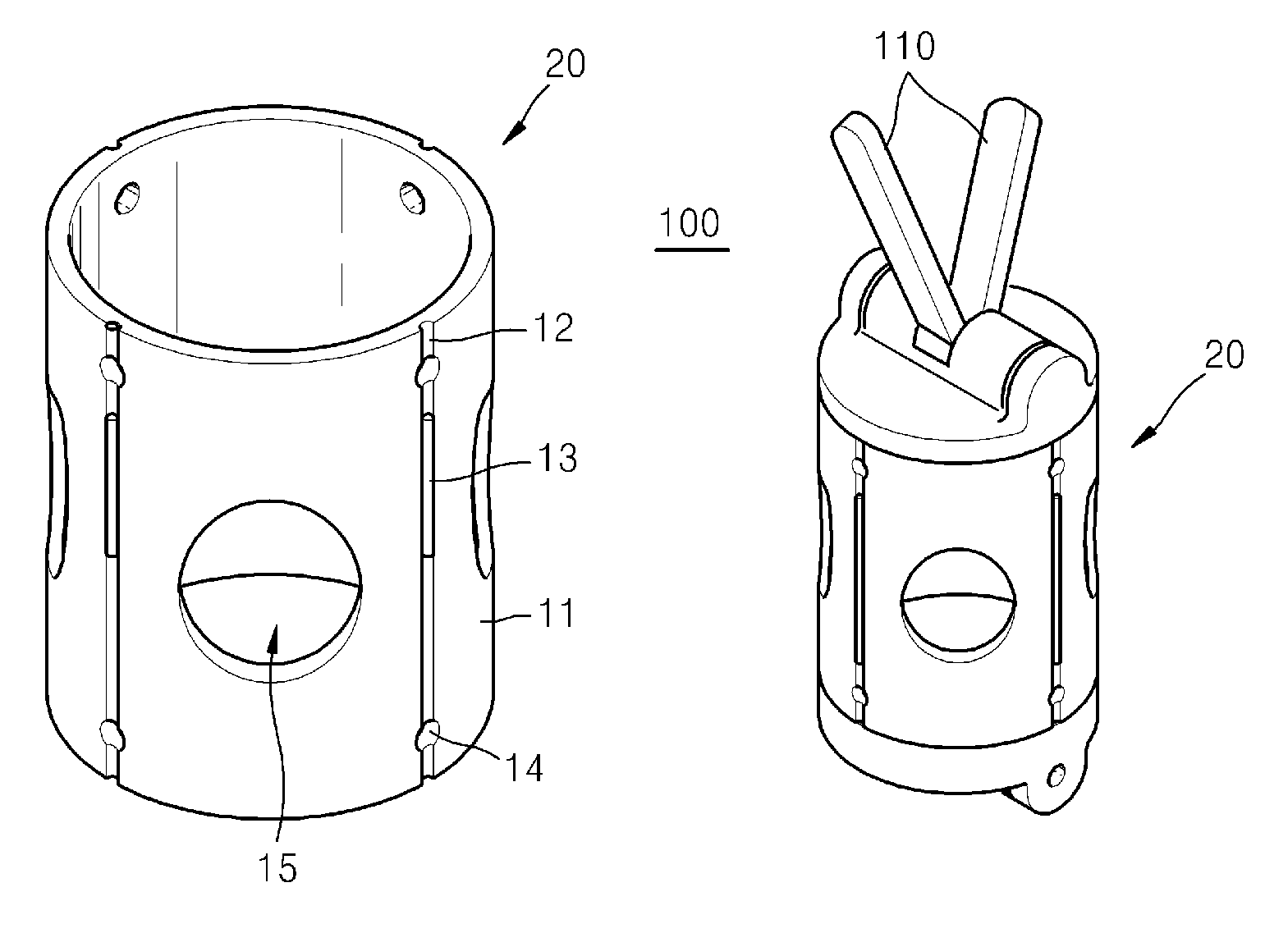
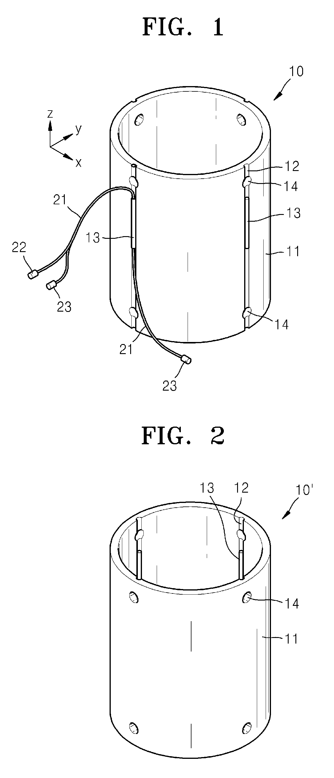
[0048]FIG. 1 is a schematic perspective view illustrating a structure of a force sensing apparatus 10 according to an embodiment. Referring to FIG. 1, the force sensing apparatus 10 may include a body 11 that has the form of a pipe and extends in an axial direction (i.e., a...


PUM

PropertyMeasurementUnit
angleaaaaaaaaaa
azimuth angleaaaaaaaaaa
angleaaaaaaaaaa

Abstract

A multi-axis force sensing apparatus that is installed at an operational end of a surgery robot and is capable of measuring force acting upon the operational end and a robot arm including the force sensing apparatus includes a body that is elastically deformable and has a pipe form extending along an axial direction of the body, an optical fiber strain gauge attached to a surface of the body to measure a tension and compression of the body in at least three directions. The optical fiber strain gauge may include at least three fiber Bragg gratings (FBGs) that are attached to the surface of the body and extended in an axial direction of the body, a light source providing light to each of the FBGs, and a light detector detecting light reflected by the FBGs or light that has passed through the FBGs.

Description

CROSS-REFERENCE TO RELATED APPLICATIONS[0001]This application claims the priority benefit of Korean Patent Application No. 10-2011-0112498, filed on Oct. 31, 2011, in the Korean Intellectual Property Office, the disclosure of which is incorporated herein in its entirety by reference.BACKGROUND[0002]1. Field[0003]The following description relates to a force sensing apparatus and a robot arm including the same, and more particularly, to a force sensing apparatus, such as a force sensing apparatus installed at an operational end of a robot arm in order to measure forces acting on the operational end of the robot arm (particularly, a three-axis force sensing apparatus capable of sensing forces of three or more degrees of freedom), and a robot arm, such as a surgery robot arm, for example, including the force sensing apparatus.[0004]2. Description of the Related Art[0005]Robots for diverse uses have been developed and commercialized in line with the advances in robot technology. For exam...

Claims


Application Information

Patent Timeline
Patent Type & Authority Patents(United States)
IPC IPC(8): G01L1/24B25J13/08G01L5/16A61B19/00
CPCB25J13/085A61B19/2203G01L1/246G01L5/166A61B2019/464A61B34/30A61B2090/064B25J19/02G01L1/24
Inventor KIM, JUN-HYUNGCHOI, HYUN-DOKIM, YEON-HOPARK, CHANG-BAE
Owner SAMSUNG ELECTRONICS CO LTD
Why Eureka
Try Eureka