Signal filtering

a signal filter and signal technology, applied in the field of signal filtering, can solve the problems of reducing the attenuation at the harmonics of the clock signal, the benefits of the circuit are rather limited, and the harmonic rejection capabilities of the lc-resonator alone are not enough for typical applications, so as to improve the harmonic rejection, and improve the harmonic rejection

Active Publication Date: 2015-11-17
TELEFON AB LM ERICSSON (PUBL)
View PDF25 Cites 18 Cited by
  • Summary
  • Abstract
  • Description
  • Claims
  • Application Information

AI Technical Summary

Benefits of technology

[0016]Therefore, the signal filter may comprise two 4-differential-path TIFs coupled in parallel. Each of the TIFs may be clocked with clock signals having four non-overlapping phases, the phases of the clock signals used for clocking the second TIF being delayed by 45 degrees with respect to the phases of the clock signals used for clocking the first TIF. The signal filter and the method of filtering a signal can enable reduced harmonic folding, higher attenuation around odd harmonics of the frequency of the clock signals and reduced sensitivity to phase errors in the clock signals, without requiring an increased oscillator frequency for generating the clock signals. The use of differential signal paths can provide rejection of all even harmonics. Such a signal filter and method of filtering a signal may be used for radio frequency (RF) narrowband bandpass filtering without inductors, and have application, for example, in low band cellular or digital television receivers where integrated inductors have previously required intolerably large silicon areas in an integrated circuit.
[0051]Alternatively, the third drive current may be equal to the in-phase component times the first constant times the square root of two, and the fourth drive current may be equal to the quadrature-phase component times the first constant times the square root of two. Such a ratio between the third drive current and the in-phase component, and between the fourth drive current and the quadrature-phase component, can enable further improved harmonic rejection.

Problems solved by technology

That, however, leads to reduced attenuation at harmonics of the clock signal, rendering the benefits of the circuit rather limited, while significantly increasing the maximum VCO frequency required for generating the LO signal.
Furthermore, the harmonic rejection capabilities of the LC-resonator alone are not enough for typical applications, for example for wireless local area network (WLAN) coexistence in cellular transceivers.

Method used


Image

  • Signal filtering
  • Signal filtering
  • Signal filtering

Examples


Embodiment Construction

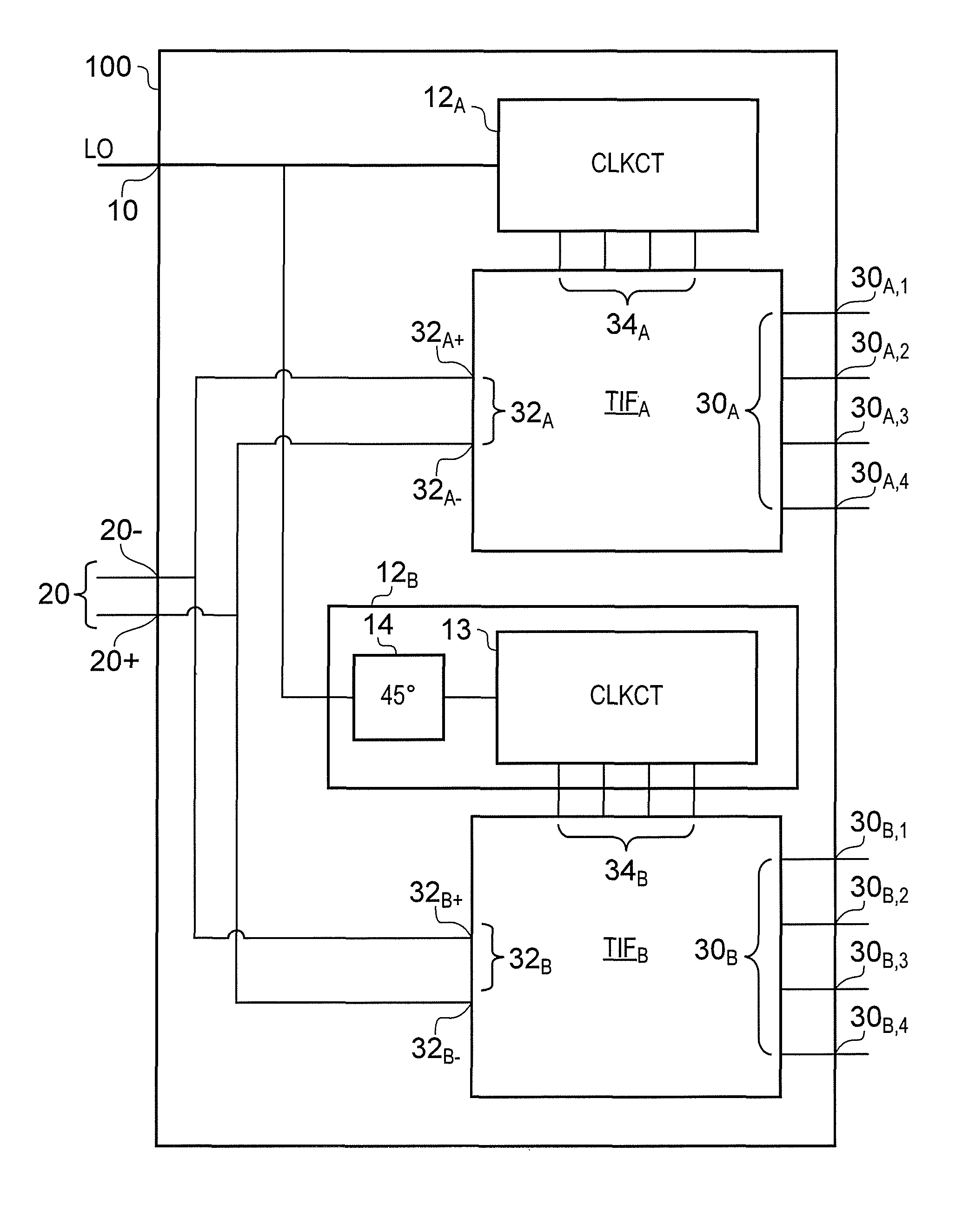
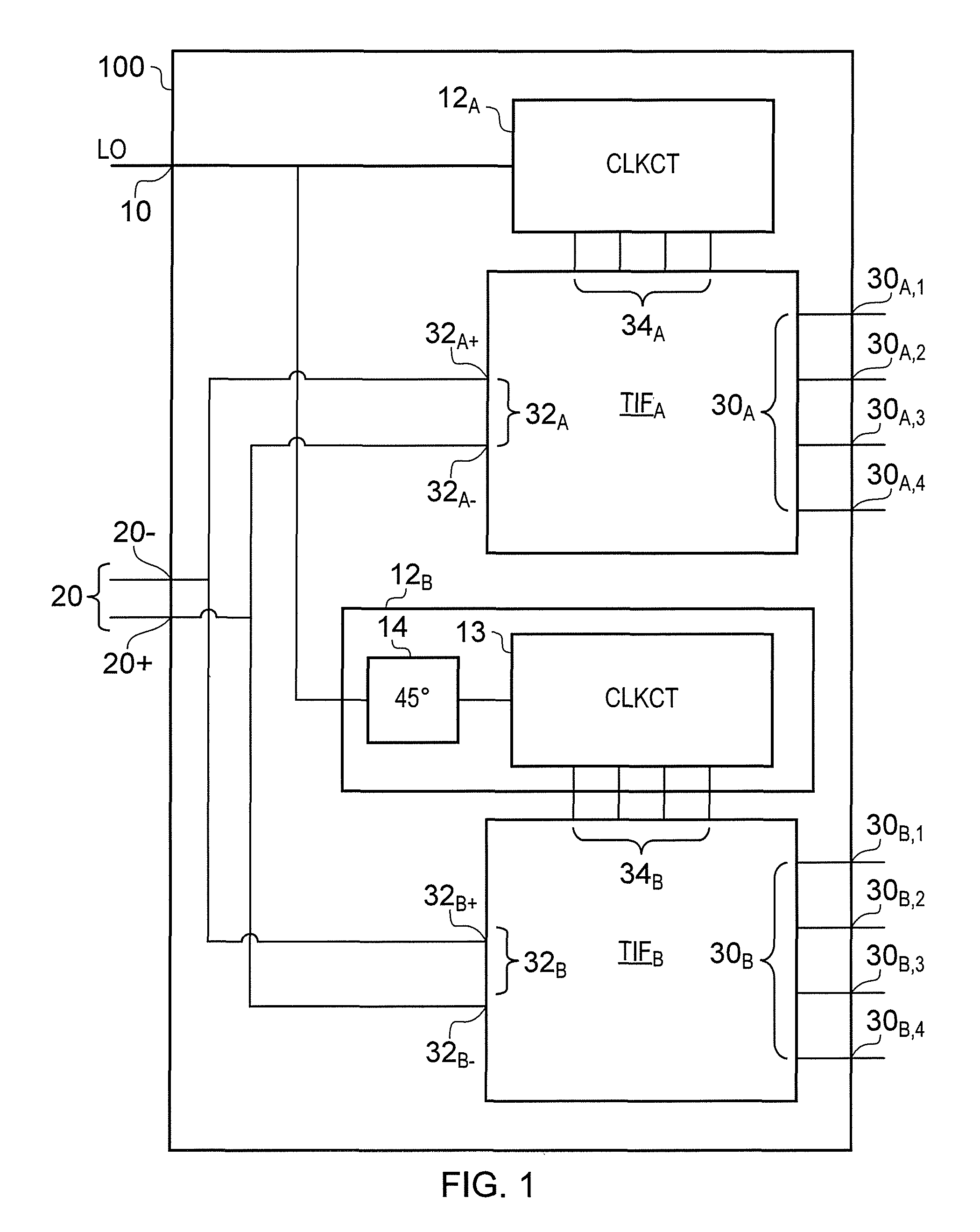
According to a first aspect, there is provided a signal filter comprising:

[0006]a first transferred impedance filter, TIF, having first, second, third and fourth first-TIF differential signal paths;

[0007]a second TIF having first, second, third and fourth second-TIF differential signal paths;

[0008]a first differential signal port of the first TIF coupled to a first differential signal port of the second TIF;

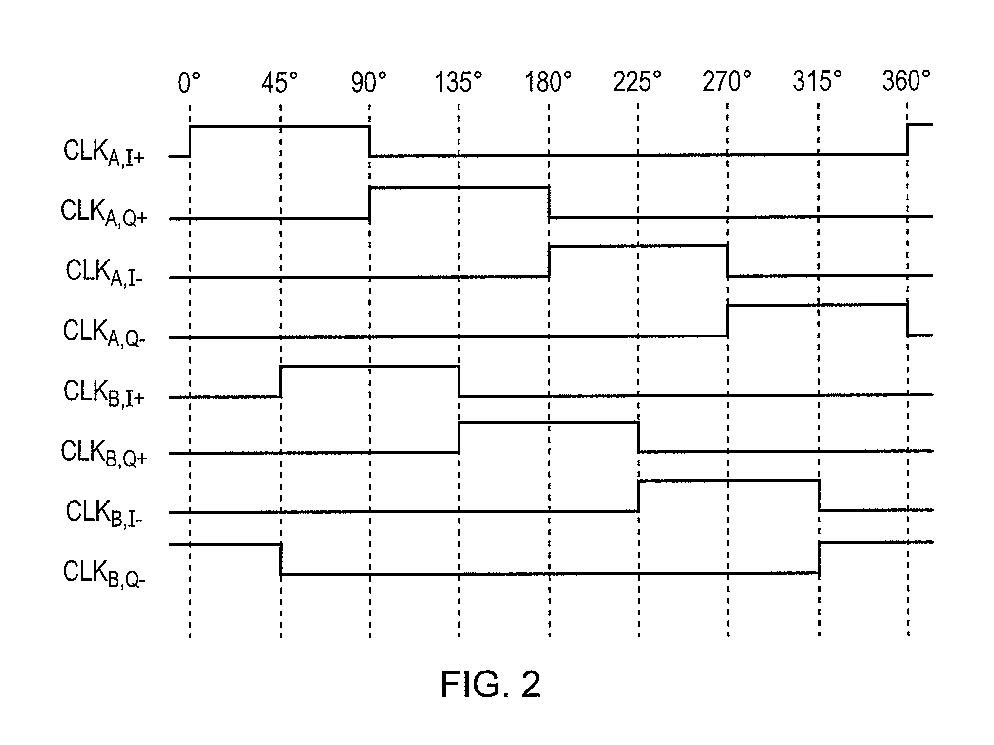
[0009]a first clock generator arranged to provide first-TIF first, second, third and fourth clock signals having non-overlapping phases for selecting, respectively, the first, second, third and fourth first-TIF differential signal paths; and

[0010]a second clock generator arranged to provide second-TIF first, second, third and fourth clock signals having non-overlapping phases for selecting, respectively, the first, second, third and fourth second-TIF differential signal paths;

[0011]wherein the phases of the second-TIF first, second, third and fourth clock signals are equal to the...


PUM


Abstract

A signal filter (100) comprises a first transferred impedance filter, TIF, (TIFA) having four differential signal paths (PA,1, PA,2, PA,3, PA,4) and a second TIF (TIFB) having four differential signal paths (PB,1, PB,2, PB,3, PB,4)- A first differential signal port of the first TIF (32A) is coupled to a first differential signal port of the second TIF (32B). A first clock generator (12A) is arranged to provide first-TIF clock signals (CLKA,I+, CLKA,Q+, CLKA,I−, CLKA,Q−) having four non-overlapping phases for selecting the respective first-TIF differential signal paths (PA,1, PA,2, PA,3, PA,4), and a second clock generator (12B) is arranged to provide second-TIF clock signals (CLKB,I+, CLKB,Q+, CLKB,J−, CLKB,Q−) having four non-overlapping phases for selecting the respective second-TIF differential signal paths (PB,1, PB,2, PB,3, PB,4). The phases of the second-TIF clock signals (CLKB,I+, CLKB,Q+, CLKB,I−, CLKB,Q−) are equal to the phases of the first-TIF clock signals (CLKA,I+, CLKA,Q+, CLKA,I−, CLKA,Q−) delayed by 45 degrees. The first-TIF first, second, third and fourth clock signals (CLKA,I+, CLKA,Q+, CLKA,I−, CLKAQ−) and the second-TIF first, second, third and fourth clock signals (CLKB,I+, CLKB,Q+, CLKB,I−, CLKB,Q−) have a duty cycle in the range 16.75% to 25%.

Description

FIELD OF THE DISCLOSURE[0001]The present disclosure relates to a signal filter, a down-conversion mixer comprising the signal filter, an up-conversion mixer comprising the signal filter, and a method of filtering a signal, having application in particular, but not exclusively, in wireless communication equipment for transmitting or receiving a radio frequency signal.BACKGROUND TO THE DISCLOSURE[0002]A transferred impedance filter (TIF), also known as a transferred impedance filter (TIF), utilising N-path filtering techniques, such as disclosed in U.S. Pat. No. 7,187,230 and in “Tunable high-Q N-path band-pass filters: modeling and verification”, A. Ghaffari et al, IEEE J. of Solid-State Circuits, May 2011, can provide narrowband bandpass filtering centred at a switching frequency, that is, a local oscillator frequency. In US 2010 / 0097258 and in “A 900-MHz direct delta-sigma receiver in 65-nm CMOS”, K. Koli et al, IEEE J. of Solid-State Circuits, December 2010, a direct delta-sigma r...

Claims


Application Information

Patent Timeline
Patent Type & Authority Patents(United States)
IPC IPC(8): H04B1/10H04B15/00H03H19/00H04B1/40H04W84/12
CPCH04B15/00H03H19/008H04B1/40H04W84/12
Inventor KOLI, KIMMO
Owner TELEFON AB LM ERICSSON (PUBL)
Why Eureka
Try Eureka