Computed tomography device and method and data storage medium for operation thereof

a computed tomography and data storage medium technology, applied in the field of computed tomography devices and methods for data storage media operation, can solve the problems of significant load on computed tomography devices, age or wear, insignificant costs, etc., and achieves short rotation time, high rotation speed, and increased load on bearings and wear.

Active Publication Date: 2015-11-24
SIEMENS HEALTHCARE GMBH
View PDF11 Cites 1 Cited by
  • Summary
  • Abstract
  • Description
  • Claims
  • Application Information

AI Technical Summary

Benefits of technology

[0008]An object of the invention is to specify a method, a data medium and a computed tomography device of the type described above with which the load on at least one technical component of the computed tomography device is reduced during operation of the computed tomography device.
[0013]According to a further embodiment of the invention the settable value for the tube current and / or the mean power consumption of the at least one x-ray tube per circuit of the rotatable part of the gantry and / or the tube voltage and / or the size of the focus on the anode of the x-ray tube is limited as the scan or operating parameter for the at least one x-ray tube. This prevents the x-ray tube being operated close to or at its load limit, thereby avoiding premature ageing due to high operating temperatures and therefore premature replacement of the x-ray tube. For example, the tube current is limited to 90% of its maximum permissible value as set by the manufacturer. The size of the focus, i.e. its flat extension on the surface of the anode, can also be limited so that it is 10% above its minimum permissible value, in order to reduce the thermal load on the anode of the x-ray tube, in particular the focal path on the anode and therefore its abrasion during operation.
[0015]According to another embodiment of the invention the settable value for the rotation speed or rotation time and / or pitch is limited as the scan or operating parameter for the at least one slip ring or the at least one bearing. A short rotation time and a high rotation speed or circuit speed or high pitch, which refers to the relationship of table advance per rotation to slice collimation, increase the load on the bearing and the wear at slip rings. Therefore if there is an upward limit for the rotation speed and a downward limit for the rotation time and / or an upward limit for the pitch, the load on the bearing(s) and slip ring(s) of the computed tomography device is reduced.

Problems solved by technology

A computed tomography device, in particular a third generation computed tomography device, embodies a number of technical components, which during operation of the computed tomography device are subject to a significant load and are therefore subject to age or wear.
Major temperature fluctuations are a particular problem, resulting in particular from secondary electrons striking the beam outlet window of the x-ray tube.
In particular x-ray tubes frequently operated close to or at their maximum permissible tube current therefore age more quickly and often have to be replaced prematurely, thereby incurring not insignificant costs.
Further technical components of the computed tomography device, which during operation at or close to their load limit are subject to increased wear, are bearings for the rotating support of the rotatable part relative to the stationary part of the gantry and slip rings for the transmission of data and / or energy between the rotatable and stationary parts of the gantry of the computed tomography device.
In order also to be able to obtain high quality image information from an adipose patient, who generally demonstrates greater beam attenuation than a patient of normal weight, the automatic dose system must frequently increase the tube current so that the x-ray tube with low reserve capacity is operated close to or at its maximum permissible tube current, with the result that it is subject to a significant load and therefore premature ageing.

Method used


Image

  • Computed tomography device and method and data storage medium for operation thereof
  • Computed tomography device and method and data storage medium for operation thereof
  • Computed tomography device and method and data storage medium for operation thereof

Examples


Embodiment Construction

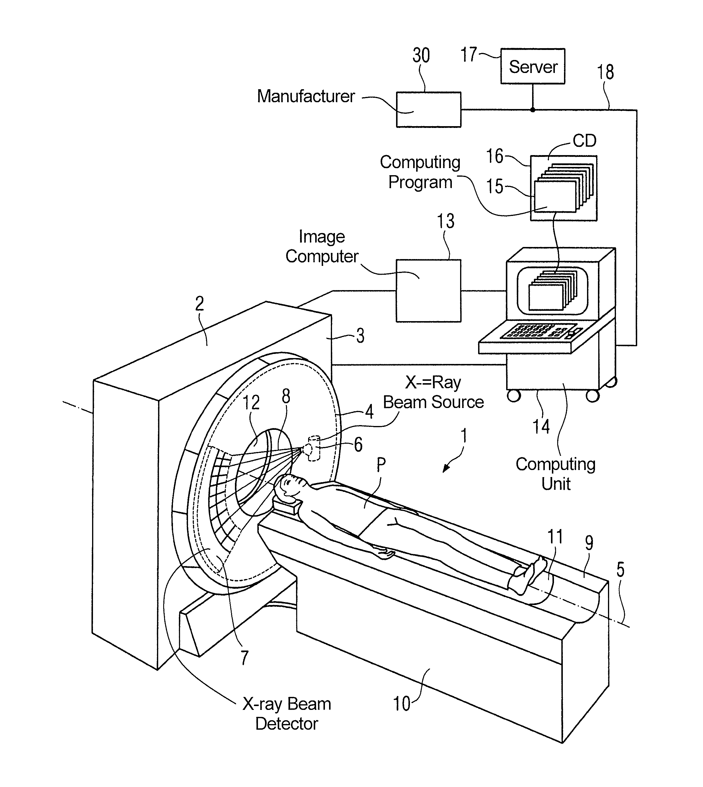
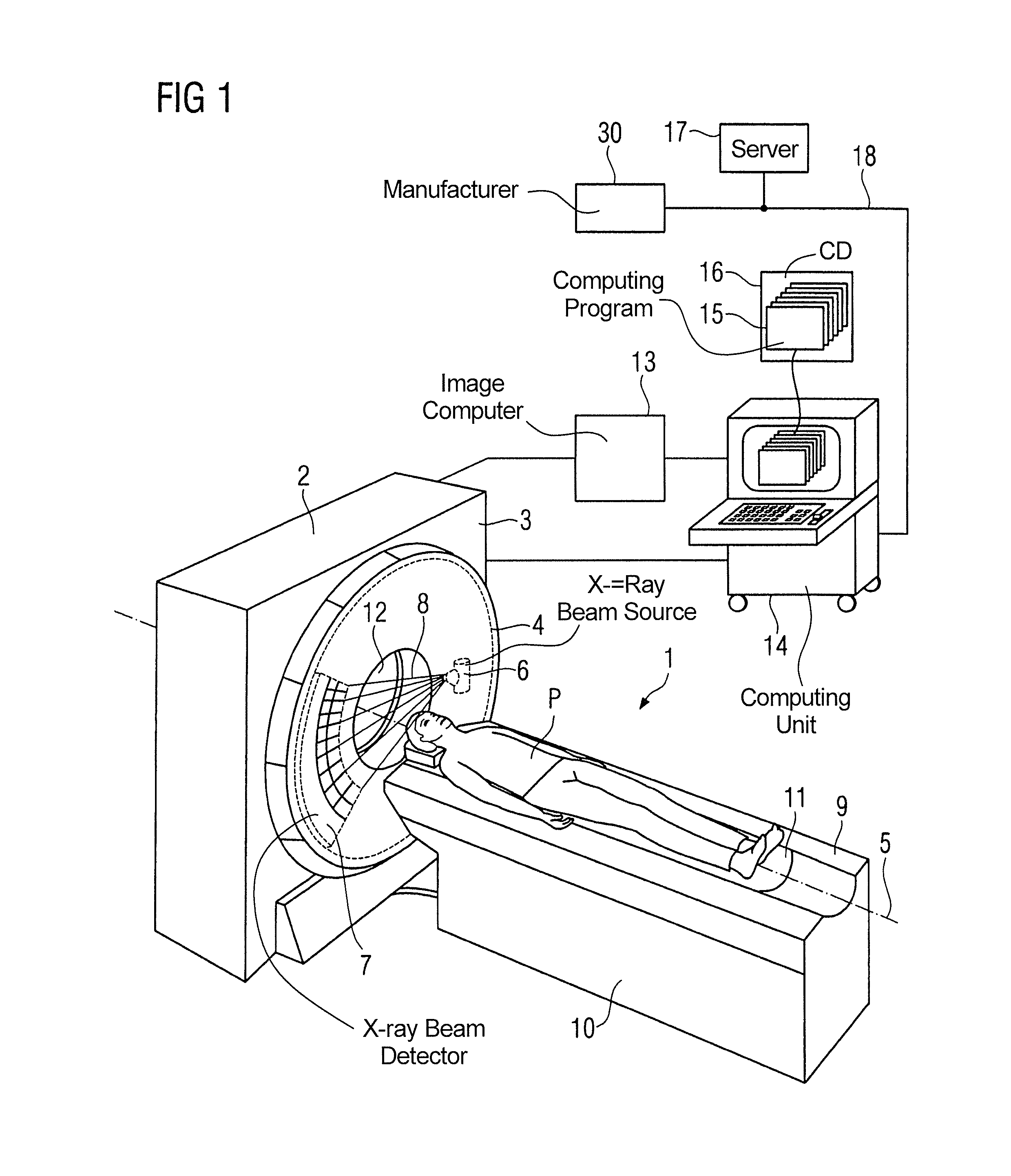
[0030]Elements that are identical or have an identical function are shown with the same reference characters in all the figures. The diagrams in the figures are schematic and not necessarily to scale. The x-ray computed tomography device 1 illustrated in FIG. 1 is only explained as far as is necessary for an understanding of the invention in the following and without restriction of generality.

[0031]The computed tomography device 1 shown in FIG. 1 has a gantry 2 with a stationary part 3 and with a schematically outlined part 4 that can be rotated about a system axis 5 and is supported by means of a bearing (not shown in FIG. 1) in a rotatable manner in relation to the stationary part 3. In the present exemplary embodiment of the invention the rotatable part 4 features an x-ray system, which comprises an x-ray beam source 6 and an x-ray beam detector 7, which are disposed facing one another on the rotatable part 4. During operation of the computed tomography device 1 x-ray radiation 8...


PUM


Abstract

In a method for operating a computed tomography device for reducing the load on at least one technical component of the computed tomography device during operation of the at least one technical component, as well as a computed tomography device and a data storage medium that implement such a method, for at least one scan parameter of the computed tomography device affecting the at least one technical component an extreme value is defined, the method being an operating mode for the computed tomography device is selected in which the settable value for the at least one scan parameter affecting the at least one technical component is limited to a certain percentage below or above the extreme value for the operation of the at least one technical component.

Description

BACKGROUND OF THE INVENTION[0001]1. Field of the Invention[0002]The present invention relates to a method for operating a computed tomography device for reducing the load on at least one technical component of the computed tomography device during operation of the at least one technical component. The invention also relates to a non-transitory computer-readable data storage medium encoded with programming instructions for implementing such a method, and a computed tomography device operable according to the method.[0003]2. Description of the Prior Art[0004]A computed tomography device, in particular a third generation computed tomography device, embodies a number of technical components, which during operation of the computed tomography device are subject to a significant load and are therefore subject to age or wear. The ageing and wear are generally greater or more marked, the closer the respective technical component is operated to its load limit.[0005]Such a technical component ...

Claims


Application Information

Patent Timeline
Patent Type & Authority Patents(United States)
IPC IPC(8): A61B6/00G06Q30/02G06Q30/00
CPCA61B6/545G06Q30/0207H01J2235/00A61B6/03G06Q30/018
Inventor HARAS, GABRIEL
Owner SIEMENS HEALTHCARE GMBH
Why Eureka
Try Eureka