
Low density subsea buoyancy and insulation material and method of manufacturing

a buoyancy and insulation material, low density technology, applied in the direction of additive manufacturing apparatus, thin material processing, domestic applications, etc., can solve the problems of reducing the efficiency of bulk processing, adding time to each project, and relying on bulk processing methods. , to achieve the effect of low density, minimal material use and density, and optimized strength

Active Publication Date: 2015-12-22
STRUCTURED MATERIALS LLC
View PDF11 Cites 7 Cited by
  • Summary
  • Abstract
  • Description
  • Claims
  • Application Information

AI Technical Summary

Benefits of technology

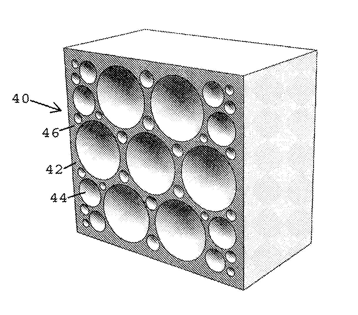
The present invention is a method of creating low density materials for use in high-pressure applications. This is achieved by additive manufacturing, printing thin layers of polymer with voids of predetermined shapes, sizes, and distribution. The voids are precisely arranged and controlled material thicknesses are used to minimize density and maximize strength. The printed material can be unitary or composed of different materials encapsulating the void spaces. Reinforcing materials can also be added for increased strength. Overall, the invention results in optimized strength, buoyancy, and insulation with minimal material usage and density.

Problems solved by technology

This is an expense and also adds time to each project.
There are numerous drawbacks to this existing material and methodology which have yet to be overcome.
A first drawback is that the bulk processing methodology relies on random arrangement of both microspheres and / or macrospheres (both of which contain a distribution of sizes) to create voids within the epoxy.
As such, theoretical maximum packing of voids is never achieved.
With the addition of macrospheres to the syntactic foam, void density can be increased further but will never result in optimum sphere packing.
A second drawback is that the spheres are permitted to touch one another or have only a minimum thickness of epoxy between them.
A third drawback is that random packing and batch processing technology allows for areas of castings to be void of epoxy.
These spaces have microspheres or macrospheres that are not properly encapsulated in epoxy, resulting in weak sections in the objects.

Method used


Image

  • Low density subsea buoyancy and insulation material and method of manufacturing
  • Low density subsea buoyancy and insulation material and method of manufacturing
  • Low density subsea buoyancy and insulation material and method of manufacturing

Examples


Embodiment Construction

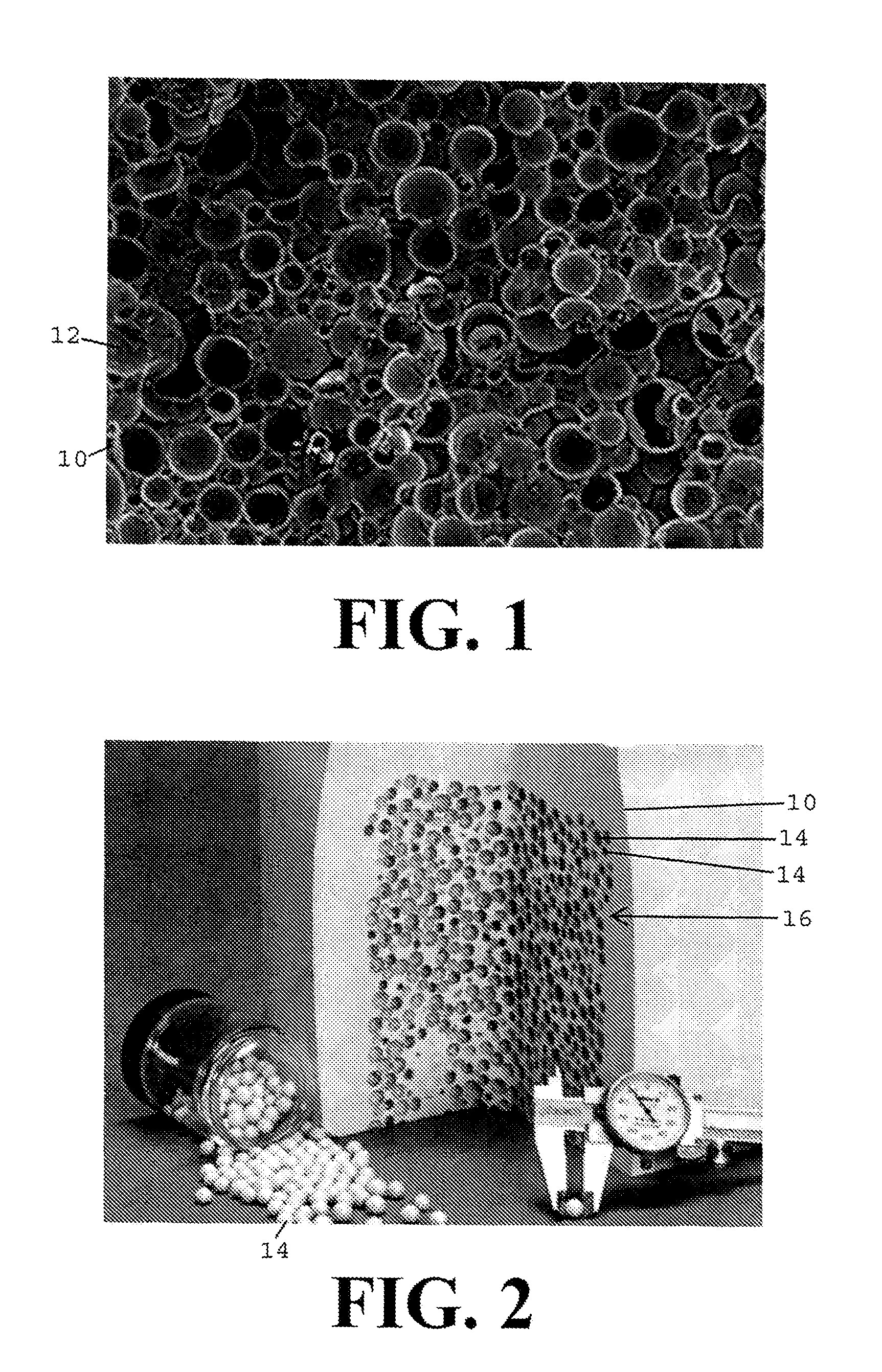
[0031]FIG. 1 is a microscopic image of a cross-section of microspheres 12 randomly mixed in epoxy 10. The image shows both the variation in size and shape of the microspheres 12, as well as the random packing of those spheres in the epoxy 10.

[0032]FIG. 2 shows macrospheres 14 of different sizes together with microsphere-filled foam in prior art syntactic foam casting 10 as well as some loose macrospheres 14. The image shows both the variation in size and shape of the macrospheres 14, as well as the random packing 16 of those spheres.

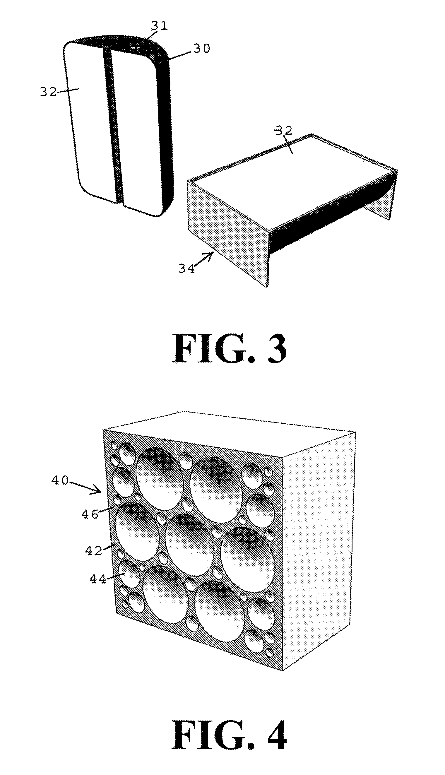
[0033]FIG. 3 shows a cutaway of a plastic shell 30 filled with foam 32 and a mold 34 containing syntactic foam 32. In this image the objects are shown with syntactic foam 32 without macrospheres. The plastic housing has a fill port 31 through which the housing is filled. Once poured and cured, the object may undergo secondary operations (like drilling of mounting holes) before being ready for shipment. The mold shown 34 is typical. Molds are often made o...


PUM

PropertyMeasurementUnit
Thicknessaaaaaaaaaa
Pressureaaaaaaaaaa
Densityaaaaaaaaaa

Abstract

The present invention relates to both a material construction and manufacturing method resulting in low density materials, especially for use as subsea buoyancy and insulation. The products are made by an additive manufacturing process, printing thin layers of a polymer material while leaving voids of precisely predetermined shapes, sizes and distribution, with precisely predetermined thicknesses between the voids. The resulting products provide optimized strength, buoyancy and insulative value with minimal material usage and density.

Description

[0001]This application claims the benefit of U.S. Provisional Application No. 61 / 682,823 filed Aug. 14, 2012, which is hereby incorporated by reference in its entirety as if fully set forth herein.BACKGROUND OF THE INVENTION[0002]Low density / high strength materials are used in subsea industries in a wide variety of applications. The primary purpose of the materials is to lend buoyancy and / or thermal insulation to equipment and structures to reduce load and / or minimize heat loss. The material of choice for this purpose is epoxy and glass microsphere-based syntactic foam. The epoxy provides strength to withstand the extreme pressures subsea. The hollow glass microspheres provide buoyancy and insulative value.[0003]This material and the processes used to manufacture and convert these materials into buoyant / insulative objects have remained essentially unchanged for over 50 years. The most common process consists of mixing epoxy resins with hollow glass microspheres (also known as microb...

Claims


Application Information

Patent Timeline
IPC IPC(8): B32B3/14B29C44/20
CPCB29C44/20Y10T428/231B29C67/20B29L2031/706B33Y80/00
Inventor COOK, TIMOTHY H.CAPOTOSTO, DAVID A.
Owner STRUCTURED MATERIALS LLC
Learn More