Hand-held power tool

a power tool and hand-held technology, applied in the field of hand-held power tools, can solve problems such as damage or destruction of the power tool housing, and achieve the effects of reducing the size of the power tool housing, and ensuring the safety of the tool

Active Publication Date: 2015-12-29
ANDREAS STIHL AG & CO KG
View PDF25 Cites 13 Cited by
  • Summary
  • Abstract
  • Description
  • Claims
  • Application Information

AI Technical Summary

Benefits of technology

[0004]It is an object of the present invention to provide a hand-held power tool of the aforementioned kind that it is of a simple configuration and has a long service life.
[0006]Instead of providing a complex coating on the bearing element, it is thus provided that the first bearing element is arranged in an intermediate element positioned in a receptacle of the power tool housing. The first bearing element is supported on a support surface relative to the bottom of the receptacle. This support surface is less than 50% of an imaginary circular ring surface that is defined between the outer circumference of the first bearing and the circumcircle about the receptacle; the term circumcircle about the receptacle is to be understood as a circle that has its center on the axis of rotation of the bearing element and that has a radius that corresponds to a spacing from the axis of rotation to a point of the receptacle that is farthest removed from the axis of rotation. Since the intermediate element is resting only with at most half of the circular ring surface on the bottom of the receptacle, the heat transfer between the bearing and the power tool housing is reduced. Because of the reduced or low heat transfer between the intermediate element and the power tool housing, it is achieved that the heat that is dissipated from the bearing first spreads uniformly within the intermediate element so that a uniform and delayed heat transfer to the power tool housing is achieved. In this way, an excessive local heating of the power tool housing can be prevented. A complex coating of the bearing is therefore not required. The support surface can be comprised of several partial surfaces wherein the indicated size of the support surface corresponds to the sum of the partial surfaces.
[0008]Advantageously, the support surface is formed by individual support locations that are separated from each other and on which the intermediate element is resting at the bottom of the receptacle in the power tool housing. By this measure, in a simple way a reduced or low heat transfer from the intermediate element into the power tool housing can be achieved. The support locations that are separated from each other, in particular in the form of separate support points, enable an excellent mechanical support action and high stability while providing a minimal support surface.
[0009]A simple configuration results when the intermediate element has at least one first rib that is resting on at least one second rib arranged at the bottom of the receptacle. In particular, the second rib crosses the first rib of the intermediate element wherein the crossing point of the first and second ribs forms of support location for the intermediate element. With such a rib structure, individual support locations can be formed in a simple way. At the same time, the ribs have a significantly enlarged surface area compared to an element that is of solid material so that the heat dissipation into the ambient air in the power tool housing is significantly improved. In order to achieve excellent heat dissipation into the air and to prevent in this way that the entire heat that has been absorbed by the intermediate element is transferred onto the power tool housing, it is provided that the intermediate element has a plurality of recesses extending in the direction of the axis of rotation of the drive shaft. In this way, the surface area is enlarged and the heat dissipation into the ambient air is thus improved. In particular, the recesses are formed as openings that extend through the intermediate element and, advantageously, are flowed through by cooling air. In this way, an active cooling action of the intermediate element by means of an air flow passing through is achieved. The power tool housing has advantageously corresponding openings in order to enable air passage through the intermediate element. The intermediate element has in particular a grid-shaped structure that is formed by first and third ribs that cross each other. In this connection, a single first rib or a single third rib may be sufficient when at the same time several third ribs or several first ribs are present, respectively. The grid-shaped structure realizes in a simple way a plurality of openings for cooling air, a large surface area for excellent heat dissipation, a high stability, and a minimal support surface in the power tool housing.
[0010]Advantageously, the first ribs project in at least one direction past the third ribs. Only the first ribs but not the third ribs are thus employed at a corresponding side as a contact point to the power tool housing or to the bearing. A simple design results when the first ribs extend, relative to the axis of rotation of the drive shaft, in outward direction, in particular radially relative to the axis of rotation of the drive shaft, and when the third ribs are formed to be annular, in particular have a circular ring shape. A shape that deviates from a circular shape, for example, an elliptical shape, is possible also. Advantageously, the intermediate element is approximately disk-shaped. The first ribs are projecting with their outwardly facing end faces past the outwardly positioned third rib and with their inwardly facing end faces past the inwardly positioned third rib; the inwardly positioned end faces of the first ribs delimit a receiving space for the first bearing. The contact to the first bearing is thus not provided across the entire circumferential surface but only provided by means of the end faces of the first ribs that project past the inwardly positioned third rib. It may be advantageous to provide a single third rib so that the outwardly positioned third rib and the inwardly positioned third rib are one and the same.
[0012]Advantageously, the drive shaft is supported by means of a second bearing that is secured in a drive shaft housing. In order to achieve excellent cooling of the drive shaft housing and thus also of the bearing location, it is provided that the drive shaft housing has at least one cooling rib on its exterior side. The second bearing is advantageously the bearing that has a greater spacing relative to the tool member than the first bearing so that sufficient space is provided for guiding the cooling air. Adjacent to the drive shaft housing there is advantageously at least one first flow guiding rib that guides a cooling air flow, conveyed by a fan wheel, past the at least one cooling rib. In particular, at least one second flow guiding rib is provided which guides the cooling air flow across at least a section of the exterior side of the first flow guiding rib that is facing away from the cooling rib. By deflection of the cooling air flow by means of the second flow guiding rib, an excellent heat dissipation away from the drive shaft housing can be achieved.

Problems solved by technology

A problem in this regard is the heat developed in operation that may cause damage or destruction of the power tool housing.

Method used


Image

  • Hand-held power tool
  • Hand-held power tool
  • Hand-held power tool

Examples


Embodiment Construction

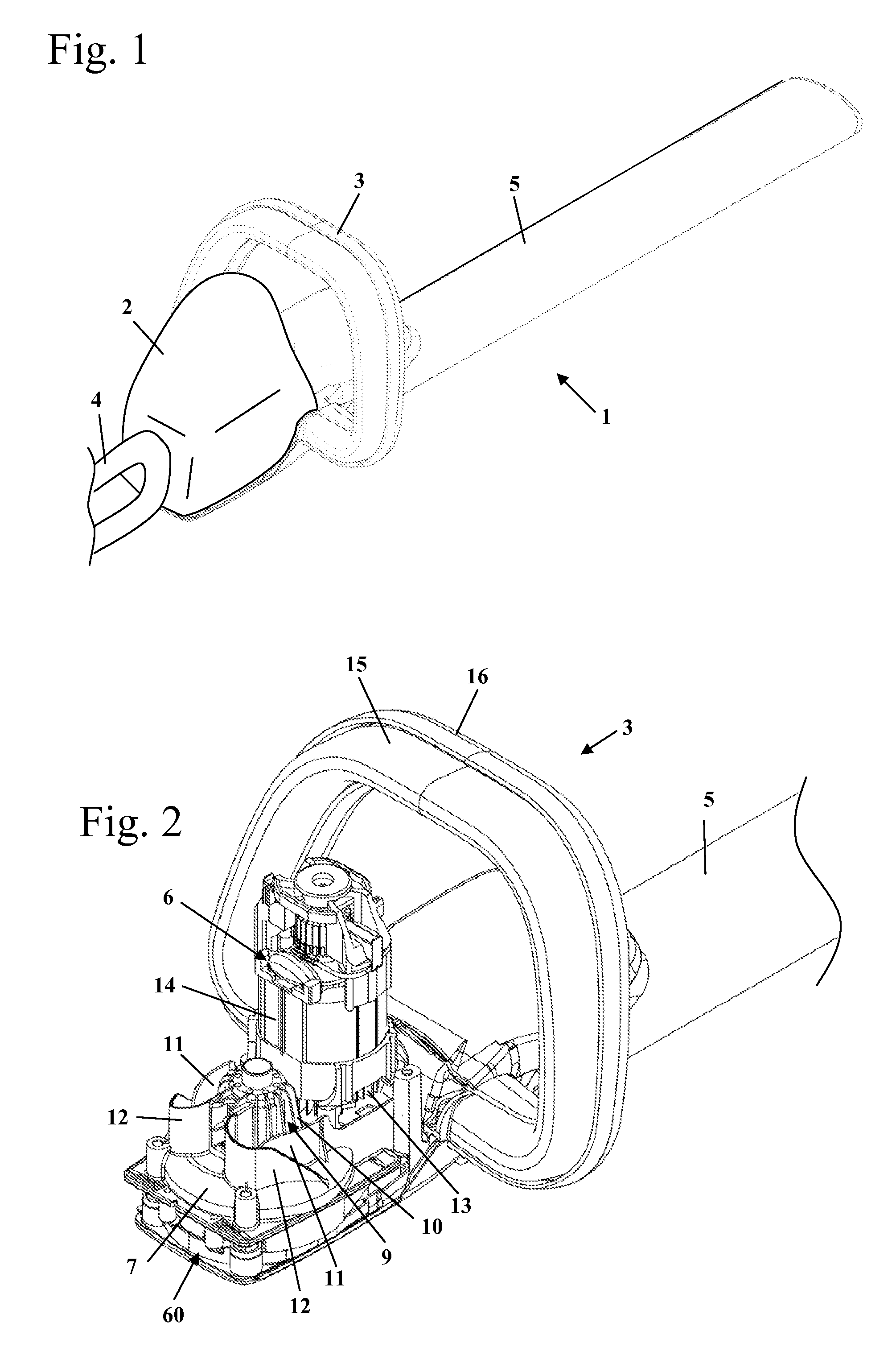
[0024]FIG. 1 shows as an embodiment of a hand-held power tool a hedge trimmer 1. The configuration of the present invention can however also be used for other hand-held power tools, in particular hand-held power tools with an electrical drive motor.

[0025]The hedge trimmer 1 has a power tool housing 2, only schematically shown in FIG. 1, on which a rear handle 4 is arranged. At the end of the power tool housing 2 opposite the handle 4, a tool member projects forwardly, i.e., a cutter bar, that in the illustration of FIG. 1 is sheathed by a protective cover 5. In the area of the attachment of the cutter bar to the power tool housing 2, a bow-shaped grip 3 is secured to the power tool housing 2.

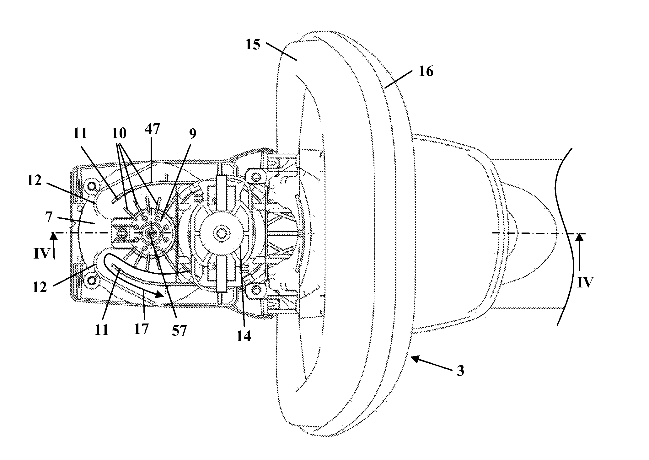
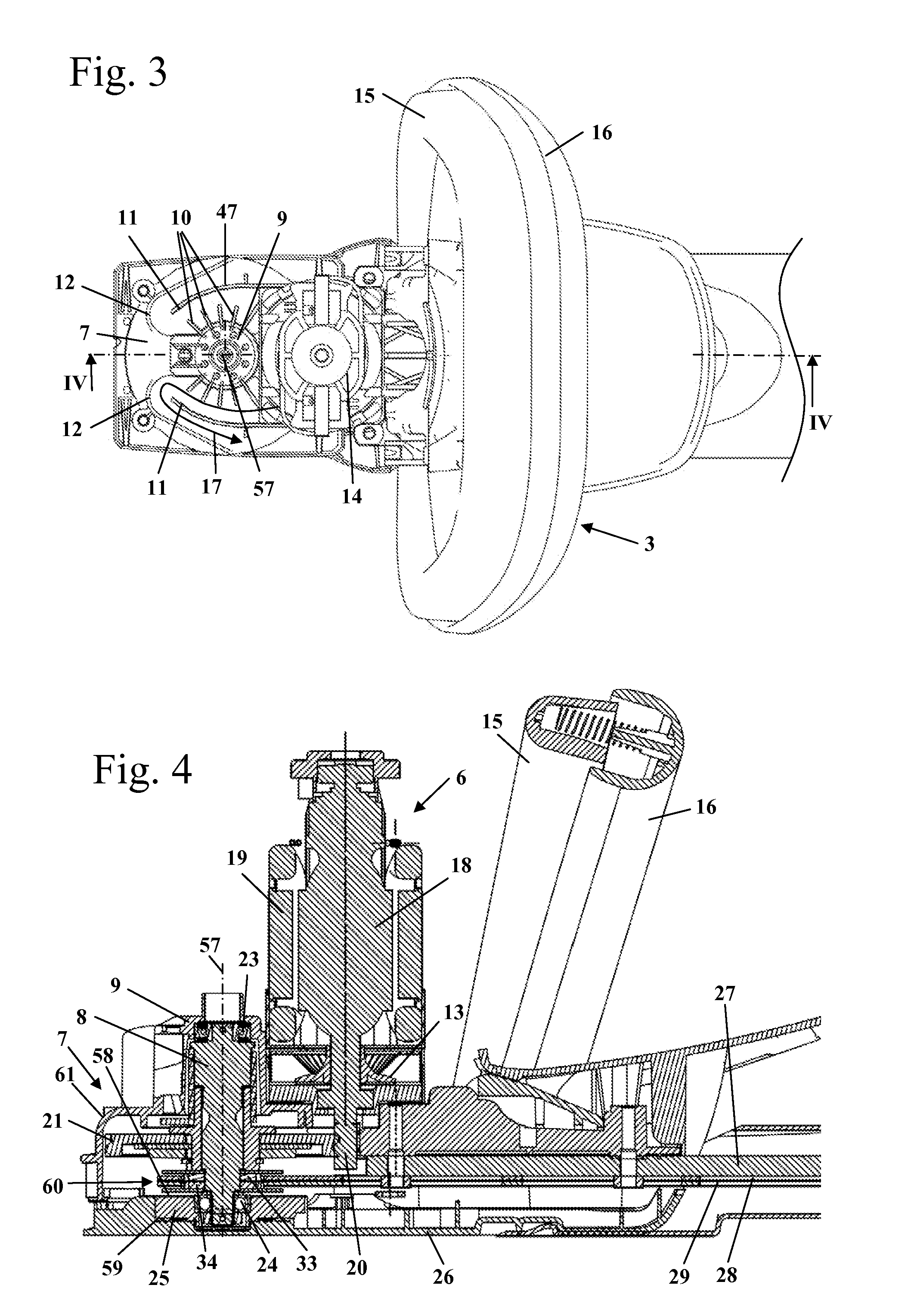
[0026]As shown the FIG. 2, the bow-shaped grip 3 is of a two-part configuration and has a first grip part 15 and a second grip part 16. The first grip part 15 is pivotably supported on the second grip part 16, is spring-loaded relative to it, and serves as a safety feature. When the two grip par...


PUM


Abstract

A hand-held power tool has a power tool housing made at least partially of plastic material. A drive motor is arranged in the power tool housing and a drive shaft driven connected to the drive motor is provided. A tool member is connected to the drive shaft and driven by the drive motor through the drive shaft. A first bearing rotatably supports the drive shaft relative to the power tool housing. An intermediate element supports the first bearing relative to the power tool housing. The intermediate element is arranged in a receptacle of the power tool housing and is supported on a support surface relative to the bottom of the receptacle. The support surface is less than approximately 50% of an imaginary circular ring surface defined between an outer circumference of the first bearing and the circumcircle of the receptacle.

Description

BACKGROUND OF THE INVENTION[0001]The invention relates to a hand-held power tool, such as a hedge trimmer or the like, that has a power tool housing that at least partially is comprised of plastic material. In the power tool housing, a drive motor is arranged that drives by means of a drive shaft at least one tool member of the power tool. The drive shaft is supported rotatably by means of at least one bearing relative to the power tool housing of the power tool.[0002]It is generally known that power tool housings of hand-held power tools with a drive motor, in particular an electric drive motor, are made of plastic material. The drive shaft that drives the tool member must be supported in the power tool housing of the power tool. A problem in this regard is the heat developed in operation that may cause damage or destruction of the power tool housing.[0003]DE 23 51 204 A1 discloses an electrical machine in which between the bearing and the housing a thermal insulation zone is provi...

Claims


Application Information

Patent Timeline
Patent Type & Authority Patents(United States)
IPC IPC(8): E21B3/00A01G3/053E21B19/18E21B19/16B25F5/00B25F5/02E21B17/22
CPCA01G3/053B25F5/02B25F5/008
Inventor KRATZIG, DAVIDMANG, HARALDUNTERMANN, ARNEDREXLER, STEFFEN
Owner ANDREAS STIHL AG & CO KG
Why Eureka
Try Eureka