Drill tool

a technology of drill bit and cutting edge, which is applied in the direction of twist drill, cutting insert, manufacturing tools, etc., can solve the problems of affecting the processing performance of the drill bit, affecting the effective cutting edge length of the inner insert, and the above-mentioned ratio of effective cutting edge length, etc., to achieve the effect of improving processing performance, ensuring the effect of cutting edge length and outstanding strength and durability

Active Publication Date: 2015-12-29
TAEGUTEC
View PDF22 Cites 0 Cited by
  • Summary
  • Abstract
  • Description
  • Claims
  • Application Information

AI Technical Summary

Benefits of technology

[0011]The inner and outer inserts of the drill tool according to the present invention are chamfered at their radially inward side and radially outward side, respectively, when mounted in the drill body, and arranged in the drill body so that the ratio of the effective cutting edge length of the inner to the outer insert satisfies 50:50. In a drill tool for small diameter holes using square-shaped inserts with four cutting edges, the ratio of the effective cutting edge lengths of the inner to outer inserts of 50:50 can be realized without reducing the size of the inscribed circle of the insert. Thus, it provides outstanding strength and durability by using the square-shaped inserts as well as improved processing performance by realizing the favorable ratio of the effective cutting edge lengths.

Problems solved by technology

Otherwise, vibrations during a processing operation are intensified and may negatively affect the processing performance of the drill due to the imbalanced force transmitted to the drill tool through the inner and outer inserts.
In an indexable insert drill for processing small diameter holes below 14 mm, there is a technical difficulty in realizing the above-mentioned ratio of the effective cutting edge lengths of the inner insert to the outer insert of 50:50 with the conventional square-shaped inserts.
The scale of a cemented carbide tool cannot be unlimitedly miniaturized due to its properties.
For example, reducing the amount of a material for the size of the insert to be smaller may weaken the insert.
However, it has drawbacks since the rectangular-shaped insert can only use two cutting edges, whereas the square-shaped insert can use four cutting edges.
Further, the strength of the rectangular-shaped insert is inferior to that of the square-shaped insert.

Method used


Image

  • Drill tool
  • Drill tool
  • Drill tool

Examples


Embodiment Construction

[0016]One embodiment of a drill tool according to the present invention will be described in detail with reference to the accompanying drawings.

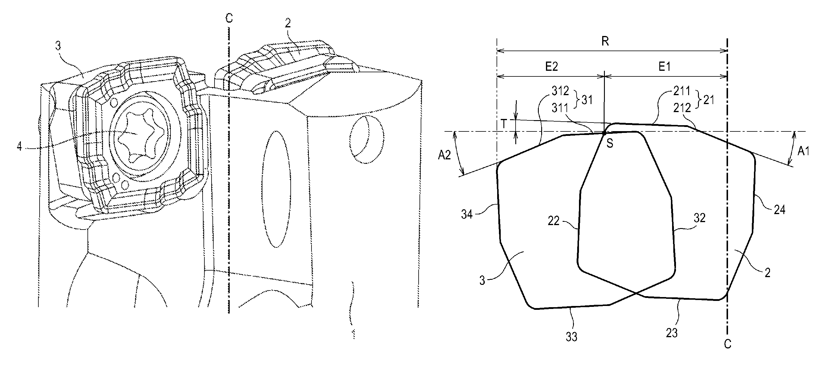
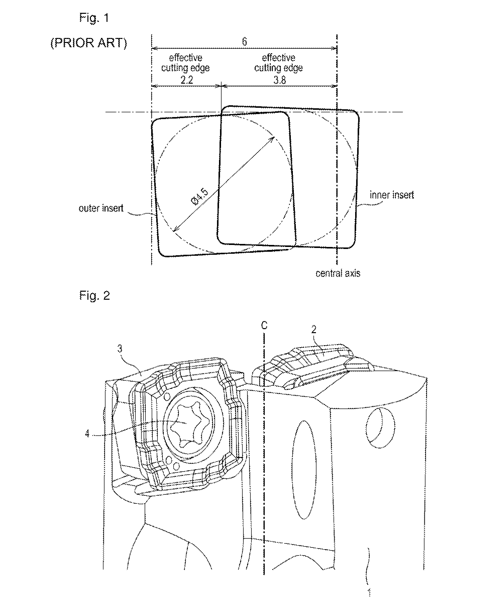
[0017]FIG. 2 shows the drill tool assembly of the present invention having a central axis C of rotation which establishes a forward to rear direction. The drill tool includes a drill body 1, and an inner insert 2 and an outer insert 3 mounted to an end portion of the drill body 1. The end portion of the drill body 1 is provided with accommodating recesses for accommodating the inner and outer inserts 2, 3. The accommodating recess for the inner insert 2 is formed adjacent to a central axis C of the drill body 1, whereas the accommodating recess for the outer insert 3 is formed at a distance from the central axis C farther than that of the inner insert 2. Since the accommodating recesses for the inner insert 2 and the outer insert 3 are at opposite side with respect to the central axis C, the inner insert 2 and the outer insert 3 can be arran...


PUM

PropertyMeasurementUnit
angleaaaaaaaaaa
angleaaaaaaaaaa
angleaaaaaaaaaa

Abstract

A drill tool including a drill body having an inner insert and an outer insert at an end portion of the drill body. The distance from a central axis of the drill body to the outer insert is greater than the distance from the central axis to the inner insert. The cutting edges of the inner and outer inserts can be chamfered with the inner insert chambered at a radially inward portion and the outer insert chamfered at a radially outward portion. The inner insert and the outer insert can be mirror symmetric to one another. The inner insert and the outer insert are mounted to the drill body such that an effective cutting length of the inner insert equals an effective cutting length of the outer insert, the effective cutting lengths being measured in a direction perpendicular to the central axis.

Description

RELATED APPLICATIONS[0001]This is a 35 USC 371 U.S. National Phase of International Application No. PCT / KR2012 / 005764, filed 19 Jul. 2012 and published in English as WO 2013 / 012266A1 on 24 Jan. 2013, which claims priority to Korean application no. 10-2011-0072059, filed 20 Jul. 2011. The contents of the aforementioned applications are incorporated by reference in their entirety.TECHNICAL FIELD[0002]The present invention generally relates to drill tools, and more particularly to a drill tool with square-shaped indexable inserts for processing small diameter holes in which the ratio of effective cutting edge length of an inner insert to effective cutting edge length of an outer insert satisfies 50:50.BACKGROUND ART[0003]Generally, a drill tool comprises a cylindrical drill body and two indexable inserts detachably mounted to an end portion of the drill body. The two indexable inserts consist of an inner insert mounted adjacent to a central axis of the drill body and an outer insert mo...

Claims


Application Information

Patent Timeline
Patent Type & Authority Patents(United States)
IPC IPC(8): B23B51/02B23B51/04B23B27/14
CPCB23B51/048B23B27/141B23B51/02B23B2200/125Y10T408/909B23B2251/285B23B2251/505Y10T408/905Y10T408/906B23B2200/204B23B51/00B23B51/08B23B27/16
Inventor BAE, BYUNG GYUN
Owner TAEGUTEC
Why Eureka
Try Eureka