Method for operating a combined gas and steam turbine system, gas and steam turbine system for carrying out said method, and corresponding control device

a combined gas and steam turbine technology, which is applied in the direction of steam engine control, lighting and heating apparatus, boiler control, etc., can solve the problems of reduced life of steam generators, inability to provide the desired increase in power solely, and inability to provide the desired increase in power quickly enough, etc., to achieve the effect of increasing system flexibility, short time and greater system benefits

Active Publication Date: 2015-12-29
SIEMENS ENERGY GLOBAL GMBH & CO KG
View PDF24 Cites 2 Cited by
  • Summary
  • Abstract
  • Description
  • Claims
  • Application Information

AI Technical Summary

Benefits of technology

[0018]Put simply, in “level control mode” the evaporator is permanently over-supplied with feed water, i.e. is actually over-fed. The resulting increased amount of feed water which has not yet evaporated must then be separated from the steam in a separator located downstream. In this way the increase in the feed water flow rate can indeed be effectively fulfilled in order to provide additional power, but under said conditions undesirable residual water collects at the evaporator outlet. Furthermore, current feed water control concepts are designed in such a way that during the switchover process between two operating modes there is no abrupt correction of the parameters. Instead a gradual and therewith relatively time-intensive transfer between two dynamic system states is conventionally provided.
[0021]It is deemed to be advantageous in this connection if a switchover is made abruptly and rapidly between the two desired overheating values, and preferably with a switching time of a maximum of one second or less. In this way the instantaneous power reserve should be available in as short a time as possible in response to frequency disruptions in the electric grid.
[0026]According to a preferred control system for implementing the inventive method a second control loop which works in parallel is provided in addition to the predictive control loop. With the aid of this second control loop a secondary desired value is determined for the feed water flow rate. A difference is then formed from the determined enthalpy of the medium at the evaporator outlet and the corresponding desired enthalpy value specification. The secondary desired value is used more or less as a correction value which is intended to further increase the accuracy of control and in cases in which the primary desired value has high errors or varies due to the system, intervenes in a correctional or stabilizing manner.
[0027]In particular when using a correction control device with which the secondary desired value is converted into an adapted relative variable, it is particularly expedient in this context to multiplicatively link together both desired values for the feed water flow rate. The effect of absolute variables on the control system can be reduced further thereby.
[0029]When returning the system to standard operation it may be advantageous to not switch rapidly back from the activation value to the normal value but to reduce the value continuously and therefore with a delay. This can occur by way of example synchronously with the increase in the power of the gas turbine if a continuous power of the entire power station is desired during this time. For this purpose the control device can be fitted at a suitable location with appropriate delay members.
[0030]The method described here for operating a waste heat steam generator and a steam turbine located downstream, with the option of liberating an instantaneous power reserve in the meantime, is preferably used in a combined gas and steam turbine system. Here this instantaneous power reserve is primarily used as a rapidly available power buffer since the additional power can be released in a relatively short time. With the aid of the power buffer a limited period can be bridged which is sufficient to at least partially compensate the delayed power increase by the gas turbine (limited by its construction- and operation-related maximum load-change speed). As a result of this measure the entire power station block makes an immediate power leap and can also lastingly maintain, or even exceed, this power level due to the simultaneously initiated power increase of the gas turbine.

Problems solved by technology

Such an undesired difference in the specific enthalpy makes control of the temperature of the live steam issuing from the steam generator difficult and leads, moreover, to high material stresses and therewith to a reduced life of the steam generator.
Under certain circumstances, however, it may be possible, in particular in the upper load range, that the desired increase in power cannot be provided solely, or cannot be provided quickly enough, by the gas turbine.
Permanent throttling of the turbine valves to provide a reserve always leads to a loss in efficiency, however, so for economic operation the degree of throttling should be kept as low as is absolutely necessary.
Furthermore, some waste heat steam generator designs, thus for example forced flow steam generators, sometimes have a significantly lower storage volume than for example natural circulation steam generators.

Method used


Image

  • Method for operating a combined gas and steam turbine system, gas and steam turbine system for carrying out said method, and corresponding control device
  • Method for operating a combined gas and steam turbine system, gas and steam turbine system for carrying out said method, and corresponding control device

Examples


Embodiment Construction

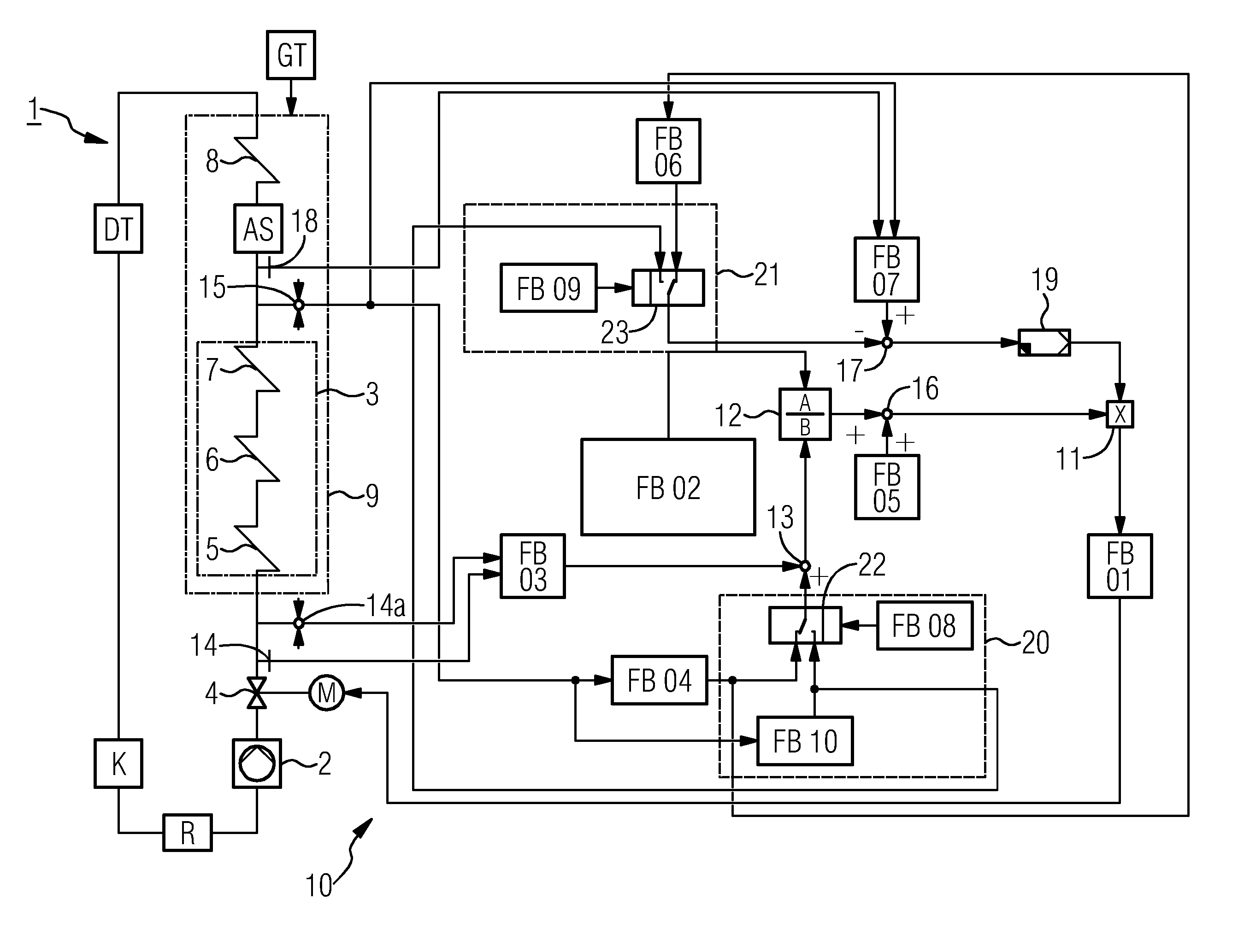
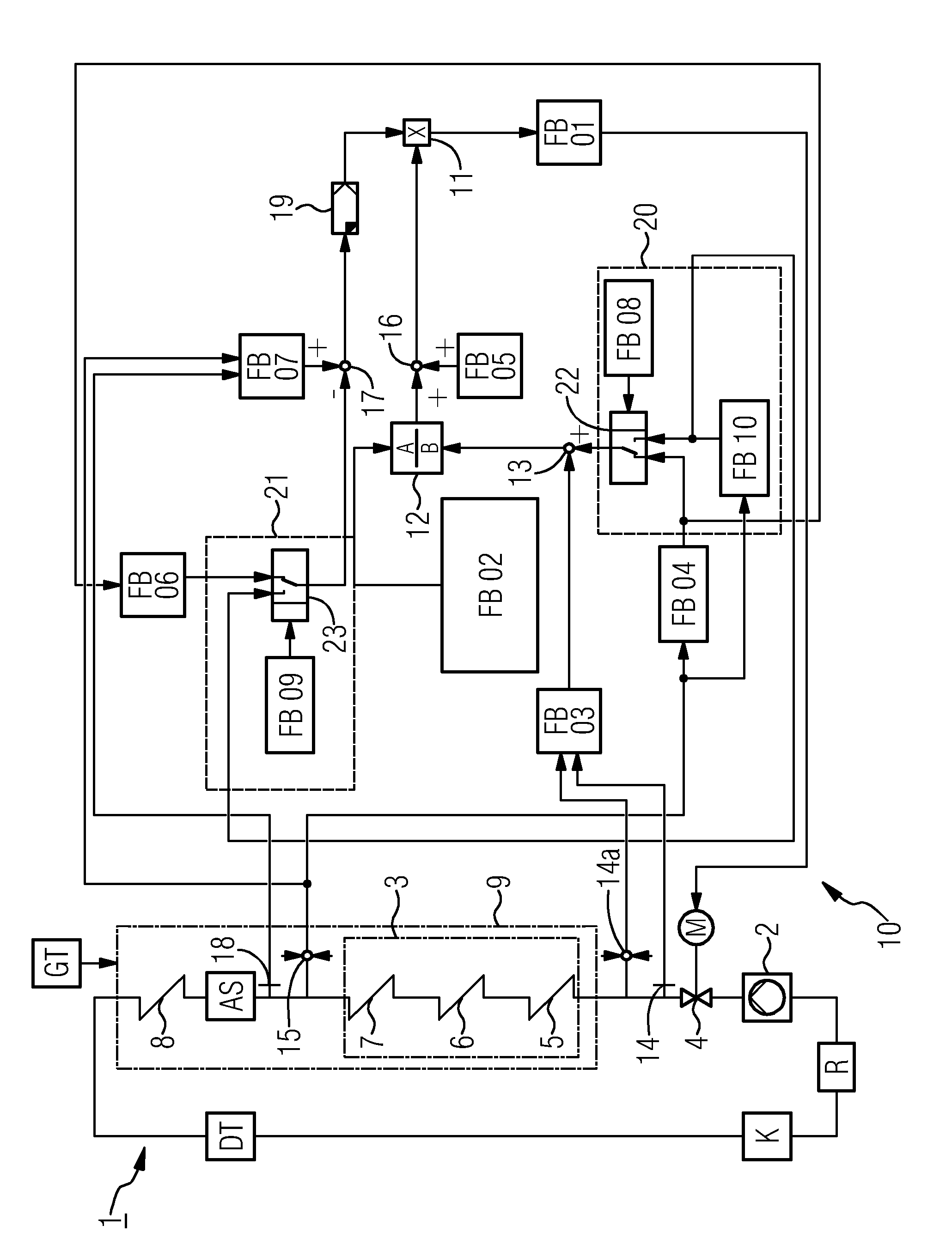
[0034]The inventive method is used in the exemplary embodiment to operate a combined gas and steam turbine system (CCGT system). For the sake of clarity a steam turbine DT with just one pressure stage is being considered here. An expansion to a plurality of pressure stages and corresponding intermediate overheating stages is possible without difficulty in this connection for the person skilled in the art.

[0035]The steam turbine DT of the CCGT system is incorporated in a feed water circuit 1. Starting from a feed water reservoir R the feed water is conveyed by means of the pump 2 into a forced flow evaporator 3. As a rule an economizer (not shown here) for pre-heating the feed water is located upstream of the evaporator. The feed water flow rate in the forced flow evaporator 3 can be varied by a control valve 4, whose valve position is adjusted by an associated servo motor M. A plurality of heating areas is provided in the forced flow evaporator 3, hereinafter also called an evaporat...


PUM


Abstract

A method of operating a combined gas and steam turbine system is provided. The system includes a gas turbine, a waste heat steam generator with an evaporator heating area, and a steam turbine. Fluid is fed to the waste heat steam generator as feed water. A primary control loop controls a feed water flow rate. Taking into account heat stored in the evaporator heating area, a primary desired value for the feed water flow rate is determined based upon a desired overheating value characteristic of a temperature by which the fluid exceeds a boiling point as the fluid exits the evaporator heating area and based upon a heat flow parameter characteristic of a heat flow transfer from fuel gas to the fluid via the evaporator heating area. The desired overheating value is lowered from a first value to a second value in order to activate an instantaneous power reserve.

Description

CROSS REFERENCE TO RELATED APPLICATIONS[0001]This application is the U.S. National Stage of International Application No. PCT / EP2011 / 067393 filed Oct. 5, 2011, and claims the benefit thereof. The International Application claims the benefits of German Application No. 10 2010 042 458.7 DE filed Oct. 14, 2010. All of the applications are incorporated by reference herein in their entirety.FIELD OF INVENTION[0002]The invention relates to a method for operating a combined gas and steam turbine system comprising a gas turbine and a waste heat steam generator which is located downstream of the gas turbine in the direction of flow of the exhaust gas or fuel gas. The invention also relates to a gas and steam turbine system arranged to carrying the method and to a corresponding control device.BACKGROUND OF INVENTION[0003]A waste heat steam generator is a heat exchanger which recovers heat from a hot flow of gas. Waste heat steam generators are used inter alia in gas and steam turbine systems ...

Claims


Application Information

Patent Timeline
Patent Type & Authority Patents(United States)
IPC IPC(8): F01K23/10F01K15/00F22B35/10
CPCF01K15/00F22B35/10F01K23/101Y02E20/16F01D15/00
Inventor BRUCKNER, JANBURGEMEISTER, ANTJETHOMAS, FRANK
Owner SIEMENS ENERGY GLOBAL GMBH & CO KG
Why Eureka
Try Eureka