Method and apparatus for estimating angles in a synchronous machine

a synchronous machine and angle estimation technology, applied in the direction of electronic commutators, dynamo-electric gear control, dynamo-electric converter control, etc., can solve the problem that the safety requirements imposed on the electrical drive of an electric vehicle or hybrid vehicle cannot always be guaranteed when using sensorless methods, and the increase of the cost of producing electrical drive systems, etc. problems, to achieve the effect of robust angle estimation and detection of fluctuations in the update frequency of measured values

Active Publication Date: 2015-12-29
ROBERT BOSCH GMBH
View PDF18 Cites 21 Cited by
  • Summary
  • Abstract
  • Description
  • Claims
  • Application Information

AI Technical Summary

Benefits of technology

[0007]The present invention therefore provides an apparatus for estimating angles in a synchronous machine, having an angle sensor device which is designed to determine event-discrete measured values for a rotor angle of a rotor of the synchronous machine and to output a measurement signal dependent on the determined measured values, an estimation device which is designed to record current and / or voltage signals from the synchronous machine, to calculate a deviation of the rotor angle of the rotor of the synchronous machine from an expected rotor angle on the basis of the recorded current and / or voltage signals and to output a deviation signal dependent on the calculated deviation, and a combining device which is designed to receive the measurement signal and the deviation signal and to calculate an estimated value for the rotor angle of the rotor of the synchronous machine from a combination of the measurement signal and the deviation signal. This makes it possible to advantageously combine two determination methods in an integrated approach, thus enabling reliable operation of the synchronous machine in all speed ranges.
[0008]The use of two methods also provides redundancy which provides increased failure safety of the angle sensor device, for example. In addition, the angle sensor device may be equipped with a low-resolution and therefore cost-effective angle sensor, in which case the associated smaller number of measured values can be compensated for by the deviation signals from the estimation device. In addition, the apparatus according to the invention provides the advantage that no additional hardware, for example additional sensors or the like, is needed with respect to the already available components of a control system for synchronous machines.
[0011]In this case, the Kalman filter may also have a determination device which is designed to determine, after the prediction value has been calculated by the prediction device, whether the measurement signal has an up-to-date measured value, the correction device being designed to calculate the correction signal on the basis of the measurement signal if the determination device determines that there is an up-to-date measured value, and the correction device being designed to calculate the correction signal on the basis of the deviation signal if the determination device determines that there is no up-to-date measured value. The use of a Kalman filter enables data fusion of measured value data from an angle sensor device and deviation data from an estimation device which resorts to current and / or voltage signals from the synchronous machine. Data fusion may advantageously prioritize the correction values used: the measured values from the angle sensor device which are updated less frequently than the deviation signals may preferably be used to calculate the correction signal for the Kalman filter if an up-to-date value is present, whereas the deviation signals from the estimation device are used to calculate the correction signal at times at which there is just no up-to-date or updated measured value. This makes it possible to intercept fluctuations in the update frequency of the measured values by means of the angle sensor devices, in particular in low speed ranges in which fewer measured values tend to be able to be recorded by the angle sensor device than in high speed ranges.
[0012]The estimation device may preferably be designed to calculate the deviation of the rotor angle on the basis of current output signals from the synchronous machine which are induced by test voltage signals injected into a supply voltage of the synchronous machine. This procedure is also referred to as an active test signal method. As a result, the rotor angle can be estimated in a manner decoupled from the actual supply voltage. In particular, active methods make it possible to adapt the amplitude and / or frequency of the test voltage signals to the operating state of the synchronous machine, with the result that a robust angle estimation is ensured in critical operating states or at low speeds. Moreover, the adaptation of the frequency of the test voltage signals makes it possible to ensure a sufficient frequency spacing with respect to the frequency of the supply voltage.
[0013]Alternatively, the estimation device may be designed to calculate the deviation of the rotor angle on the basis of reverse voltage signals from the synchronous machine. These methods are also referred to as passive estimation methods. One advantage is that the deviation signals can be determined from output signals from the synchronous machine which are already present anyway, without the need for active intervention in the control of the machine. In particular, the passive methods are primarily suitable for medium and higher speeds, whereas the active test signal method has an upper limit in terms of the speed.

Problems solved by technology

However, such angle sensors, in particular angle sensors with a high resolution, may give rise to considerable costs when producing electrical drive systems.
However, the known methods for determining the rotor angle are suitable only for particular restricted speed ranges.
For example, safety requirements which are imposed on the electrical drive of an electric vehicle or hybrid vehicle cannot always be ensured when using sensorless methods.
On the other hand, methods with low-resolution angle sensors are inferior to other methods in low speed ranges on account of the insufficient measurement data.

Method used


Image

  • Method and apparatus for estimating angles in a synchronous machine
  • Method and apparatus for estimating angles in a synchronous machine
  • Method and apparatus for estimating angles in a synchronous machine

Examples


Embodiment Construction

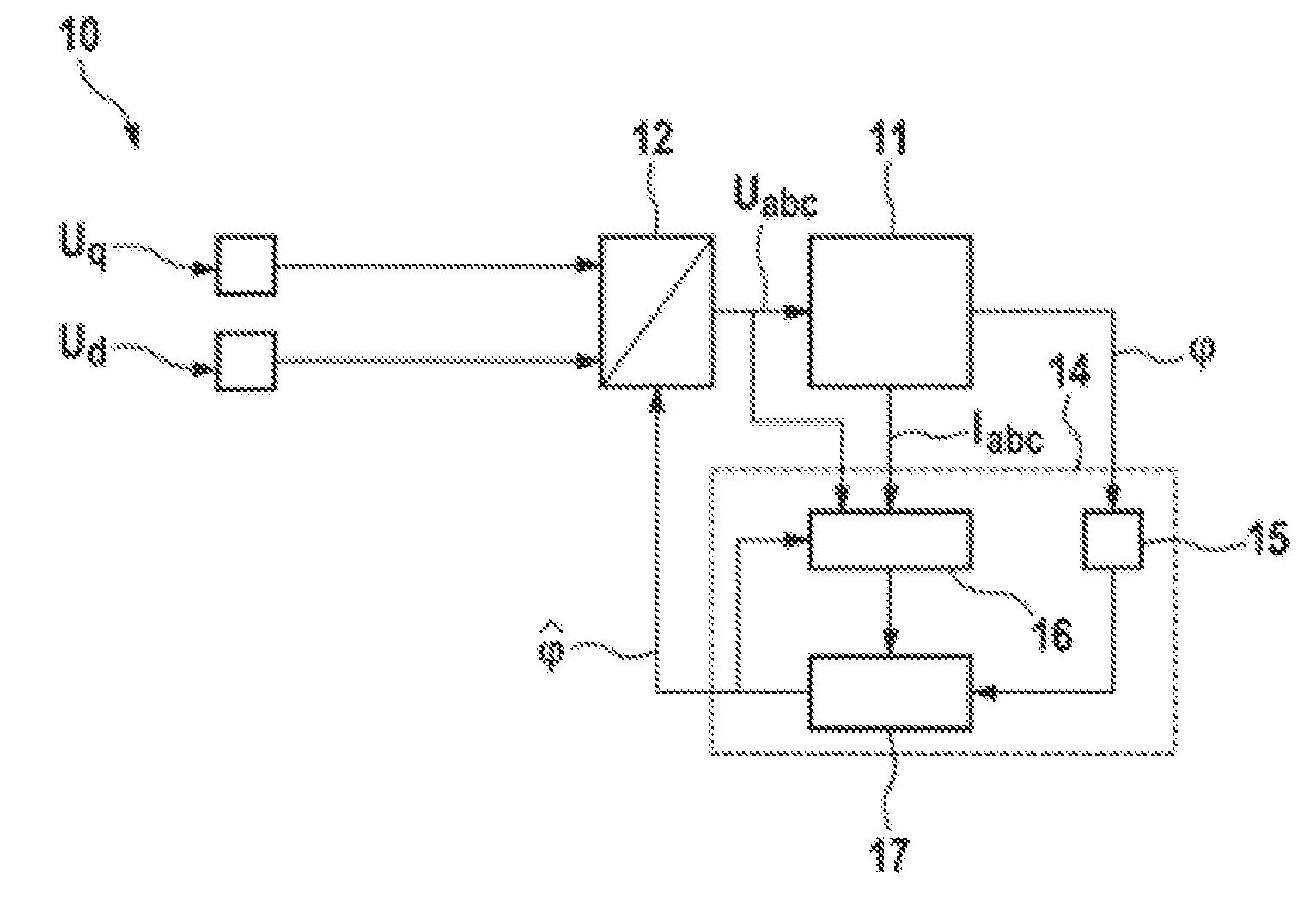
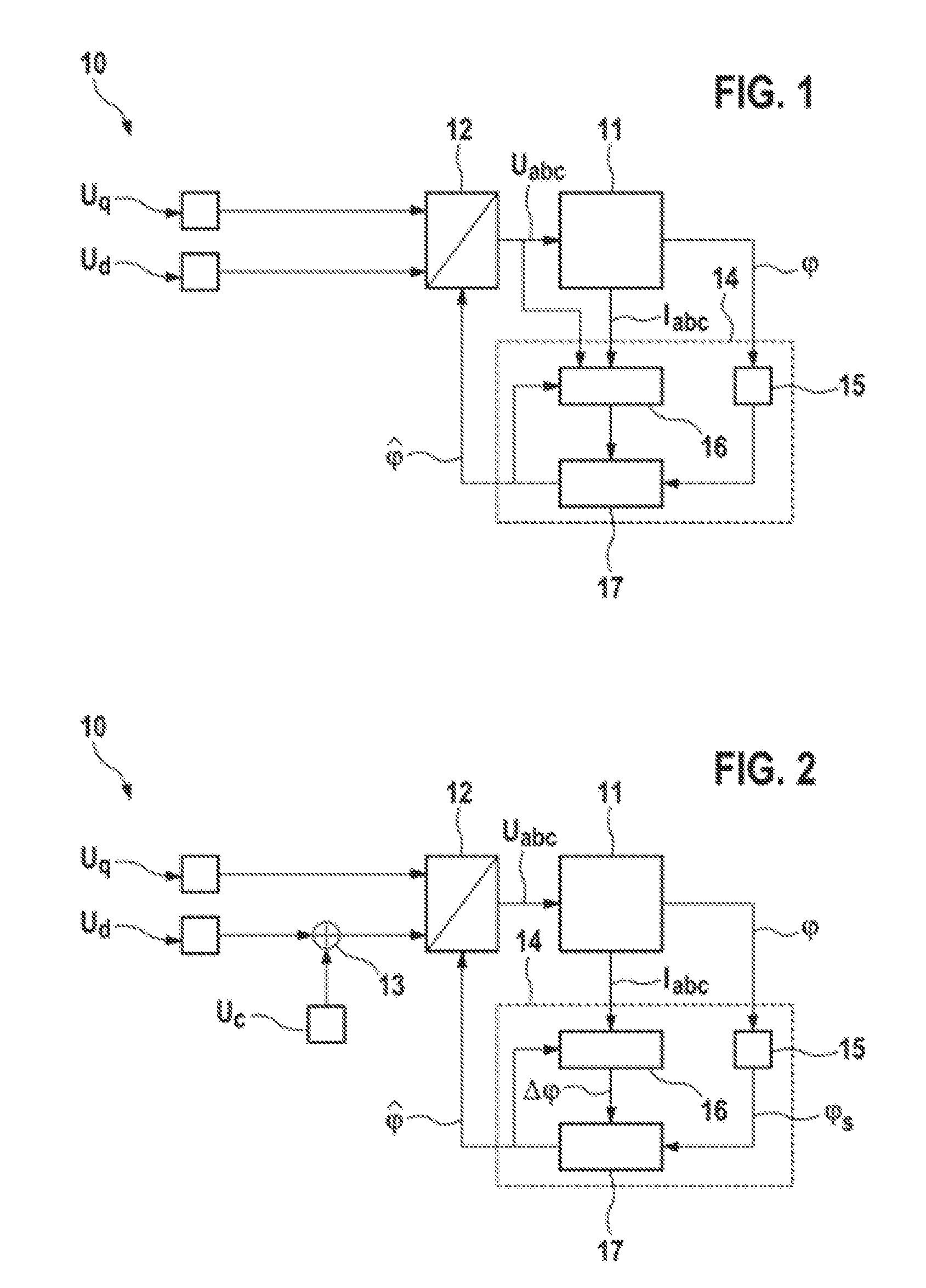
[0020]FIG. 1 shows a schematic illustration of a system 10 for estimating angles in a synchronous machine 11. In this case, the synchronous machine 11 may be a permanent-magnet synchronous machine, for example. The three-phase supply voltage Uabc for the synchronous machine 11 may be provided via a supply voltage device 12. In this case, the supply voltage device 12 may have a transformation device which can be used to transform supply voltage signals Uq, and Ud from a rotor-fixed d-q coordinate system into a stator-fixed coordinate system. The output signals from the transformation device may be supplied to a PWM signal generator which controls an inverter included in the supply voltage device 12. The three-phase supply voltage Uabc can be delivered to the synchronous machine 11 via the inverter. In this case, the torque of the synchronous machine 11 and the formation of magnetic fields by the synchronous machine 11 can be regulated using the supply voltage component Uq, whose volt...


PUM


Abstract

The invention relates to an apparatus for estimating angles in a synchronous machine (11), having an angle sensor device (15) which is designed to determine event-discrete measured values for a rotor angle (φ) of a rotor of the synchronous machine (11) and to output a measurement signal dependent on the determined measured values, an estimation device (16) which is designed to record current and / or voltage signals from the synchronous machine (11), to calculate a deviation (Δφ) of the rotor angle (φ) of the rotor of the synchronous machine (11) from an expected rotor angle on the basis of the recorded current and / or voltage signals and to output a deviation signal dependent on the calculated deviation (Δφ), and a combining device (17) which is designed to receive the measurement signal and the deviation signal and to calculate an estimated value ({circumflex over (φ)}) for the rotor angle (φ) of the rotor of the synchronous machine (11) from a combination of the measurement signal and the deviation signal.

Description

BACKGROUND OF THE INVENTION[0001]The invention relates to a method and an apparatus for estimating angles in a synchronous machine, in particular in a permanent-magnet synchronous machine.[0002]In order to operate permanent-magnet synchronous machines which are used, for example, in electrical drive technology for electrically operated vehicles such as electric vehicles or hybrid vehicles, it is necessary to know the rotor angle, that is to say the position of the rotor of the synchronous machine with respect to its rotational movement around the rotor shaft. This measurement variable is needed to match the generation of torque to the actual rotor position.[0003]The rotor angle may be determined, for example, with the aid of angle sensors. However, such angle sensors, in particular angle sensors with a high resolution, may give rise to considerable costs when producing electrical drive systems. Therefore, cost-effective angle sensors with a correspondingly lower angular resolution a...

Claims


Application Information

Patent Timeline
Patent Type & Authority Patents(United States)
IPC IPC(8): H02P1/04H02P6/16H02P6/18H02P21/14H02P25/02H02P23/12H02P23/14
CPCH02P6/183H02P6/16H02P25/023H02P23/12H02P23/14H02P21/146H02P21/18H02P25/03
Inventor LINGENFELSER, CHRISTIANMAYER-JOHN, ECKARTGOETTING, GUNTHER
Owner ROBERT BOSCH GMBH
Why Eureka
Try Eureka