Alignment methods in fluid-filled MEMS displays

a fluid-filled mems and display technology, applied in the manufacture of electrode systems, electric discharge tubes/lamps, instruments, etc., can solve the problems of inferior picture quality, and inability to achieve the full display, so as to improve the optical and electromechanical performance of the display, reduce the effect of stiction

Inactive Publication Date: 2016-01-05
SNAPTRACK
View PDF1053 Cites 13 Cited by
  • Summary
  • Abstract
  • Description
  • Claims
  • Application Information

AI Technical Summary

Benefits of technology

[0011]In addition, stiction can be reduced by having the surfaces of the display components (including front and rear surfaces of moving elements) wetted by a fluid, such as a lubricant. Various liquids and gases, when surrounding moving components of MEMS light modulators, in addition to reducing stiction, can also provide improved optical and electromechanical performance of a display.

Problems solved by technology

Backlit displays using mechanical light modulators have not yet demonstrated sufficiently attractive combinations of brightness and low power.
Misalignment of such components can lead to inferior picture quality and potentially even inoperability of the display as a whole.

Method used


Image

  • Alignment methods in fluid-filled MEMS displays
  • Alignment methods in fluid-filled MEMS displays
  • Alignment methods in fluid-filled MEMS displays

Examples


Embodiment Construction

[0041]To provide an overall understanding of the invention, certain illustrative embodiments will now be described, including apparatus and methods for displaying images. However, it will be understood by one of ordinary skill in the art that the systems and methods described herein may be adapted and modified as is appropriate for the application being addressed and that the systems and methods described herein may be employed in other suitable applications, and that such other additions and modifications will not depart from the scope hereof.

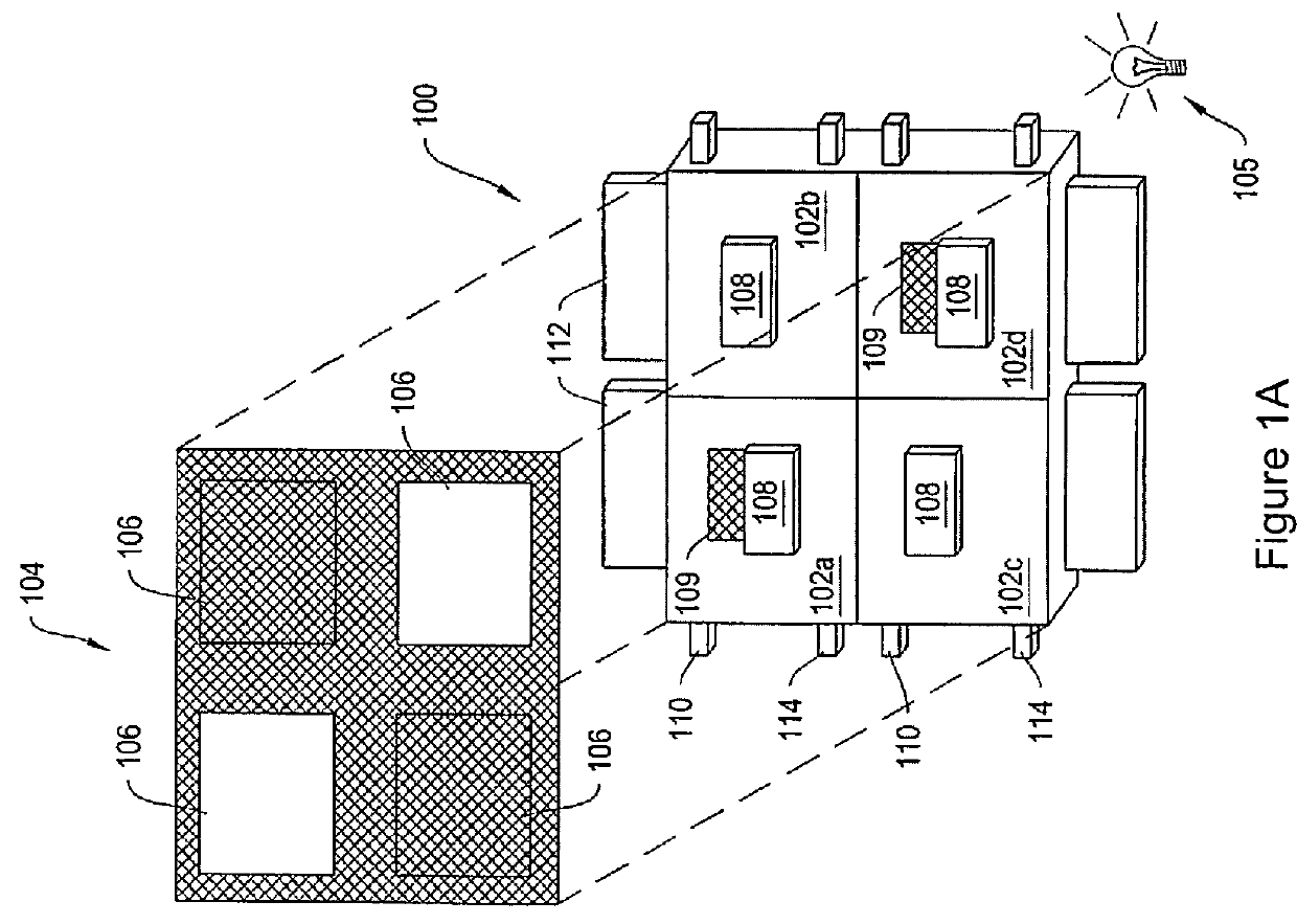
[0042]FIG. 1A is a schematic diagram of a direct-view MEMS-based display apparatus 100, according to an illustrative embodiment of the invention. The display apparatus 100 includes a plurality of light modulators 102a-102d (generally “light modulators 102”) arranged in rows and columns. In the display apparatus 100, light modulators 102a and 102d are in the open state, allowing light to pass. Light modulators 102b and 102c are in the closed st...


PUM

PropertyMeasurementUnit
dielectric constantaaaaaaaaaa
frequenciesaaaaaaaaaa

Abstract

This invention relates to MEMS display apparatus and methods for assembly thereof that include a plurality of light modulators having components substantially surrounded in a liquid that reduces the effects of stiction and improves the optical and electromechanical performance of the display apparatus. The invention also relates to methods for aligning components of a MEMS display to establish a correspondence between the plurality of light modulators and a plurality of apertures to regulate the transmission of light through the apparatus.

Description

CROSS-REFERENCE TO RELATED APPLICATIONS[0001]This application claims priority to and benefit of U.S. Provisional Patent Application No. 60 / 930,872, entitled “MEMS Displays and Assembly Methods” and filed on May 18, 2007, and is a continuation-in-part of U.S. patent application Ser. No. 11 / 656,307, entitled “Methods and Apparatus for Actuating Displays” and filed on Jan. 19, 2007, which is a continuation-in-part of U.S. patent application Ser. No. 11 / 251,035, entitled “Methods and Apparatus for Actuating Displays” and filed on Oct. 14, 2005, which is a continuation-in-part of U.S. patent application Ser. No. 11 / 218,690, entitled “Methods and Apparatus for Spatial Light Modulation” and filed on Sep. 2, 2005, which claims priority to and benefit of U.S. Provisional Patent Application No. 60 / 676,053, entitled “MEMS Based Optical Display” and filed on Apr. 29, 2005, and U.S. Provisional Application 60 / 655,827, entitled “MEMS Based Display Modules” and filed on Feb. 23, 2005. This applica...

Claims


Application Information

Patent Timeline
Patent Type & Authority Patents(United States)
IPC IPC(8): G02B26/00G02B26/08G09G3/34B81C3/00
CPCG02B26/0841B81C3/004G02B26/00G09G3/3433G09G3/3473B81B2201/047B81B2203/0315B81C2203/019B81C2203/0118B81C2203/051G09G2300/023G09G2300/0426G09G2300/0443G09G2300/0842H01L2924/1461G02B26/023
Inventor HAGOOD, NESBITT W.FIJOL, JOHN J.STEYN, JASPER LODEWYKPAYNE, RICHARD S.GANDHI, JIGNESH
Owner SNAPTRACK
Why Eureka
Try Eureka