Electric double-layer capacitor, and current collector for electric double-layer capacitor

a current collector and capacitor technology, applied in the direction of electrolytic capacitors, liquid electrolytic capacitors, transportation and packaging, etc., can solve the problems of significant deterioration of the internal resistance of the coated electrode at 85° c., increase in the internal pressure of the container housing the polarized electrode and electrolyte solution, etc., to achieve easy handling during manufacture and change in internal resistance

Active Publication Date: 2016-01-12
NIPPON CHIMI CON CORP
View PDF21 Cites 0 Cited by
  • Summary
  • Abstract
  • Description
  • Claims
  • Application Information

AI Technical Summary

Benefits of technology

[0017]According to the electric double-layer capacitor of the present invention, an elastomer having an expansion rate of 50% or less in γ-butyrolactone at 85° C. after 100 hours was employed, therefore large expansion of the binding agent in the electrode material because of γ-butyrolactone comprised in the electrolyte solution is prevented. As a result, change in internal resistance, which seems to arise from the spreading of distance between electrode materials such as activated carbon due to expansion of the binding agent can be suppressed. In addition, handling during manufacture becomes easy since water can be used as the solvent for coated electrode.

Problems solved by technology

However, in an electrolyte solution that employs carbonate solvent, there is a problem that the internal pressure of the container housing the polarized electrode and electrolyte solution increases due to carbon monoxide (CO) gas generated from the degradation of the solvent under high temperatures.
In other words, as shown in FIG. 4, loading experiments spanning 500 hours at each temperatures of 60° C., 70° C., and 85° C. were performed for each of the coated electrode and the sheet electrode to measure the change in capacity and internal resistance, and it was found that only the internal resistance of the coated electrode at 85° C. was significantly deteriorated in property.

Method used


Image

  • Electric double-layer capacitor, and current collector for electric double-layer capacitor
  • Electric double-layer capacitor, and current collector for electric double-layer capacitor
  • Electric double-layer capacitor, and current collector for electric double-layer capacitor

Examples


examples

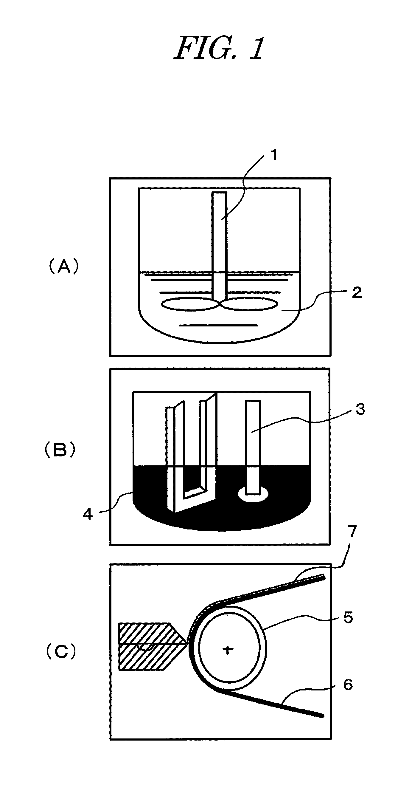
[0033]The present invention will now be further specifically described below with Examples. The diagram of the slurry preparation steps in Examples and Comparative Examples is shown in FIG. 1.

example

[0034]Carboxymethylcellulose-sodium salt (CMC-Na) as the dispersing agent and pure water as the solvent are mixed (reference symbol 2 in the FIG. 1), and stirred by a stirring machine 1. Since CMC-Na is powder, it is dissolved in water in advance so that it will be easy to handle in the next step (FIG. 1 (A)).

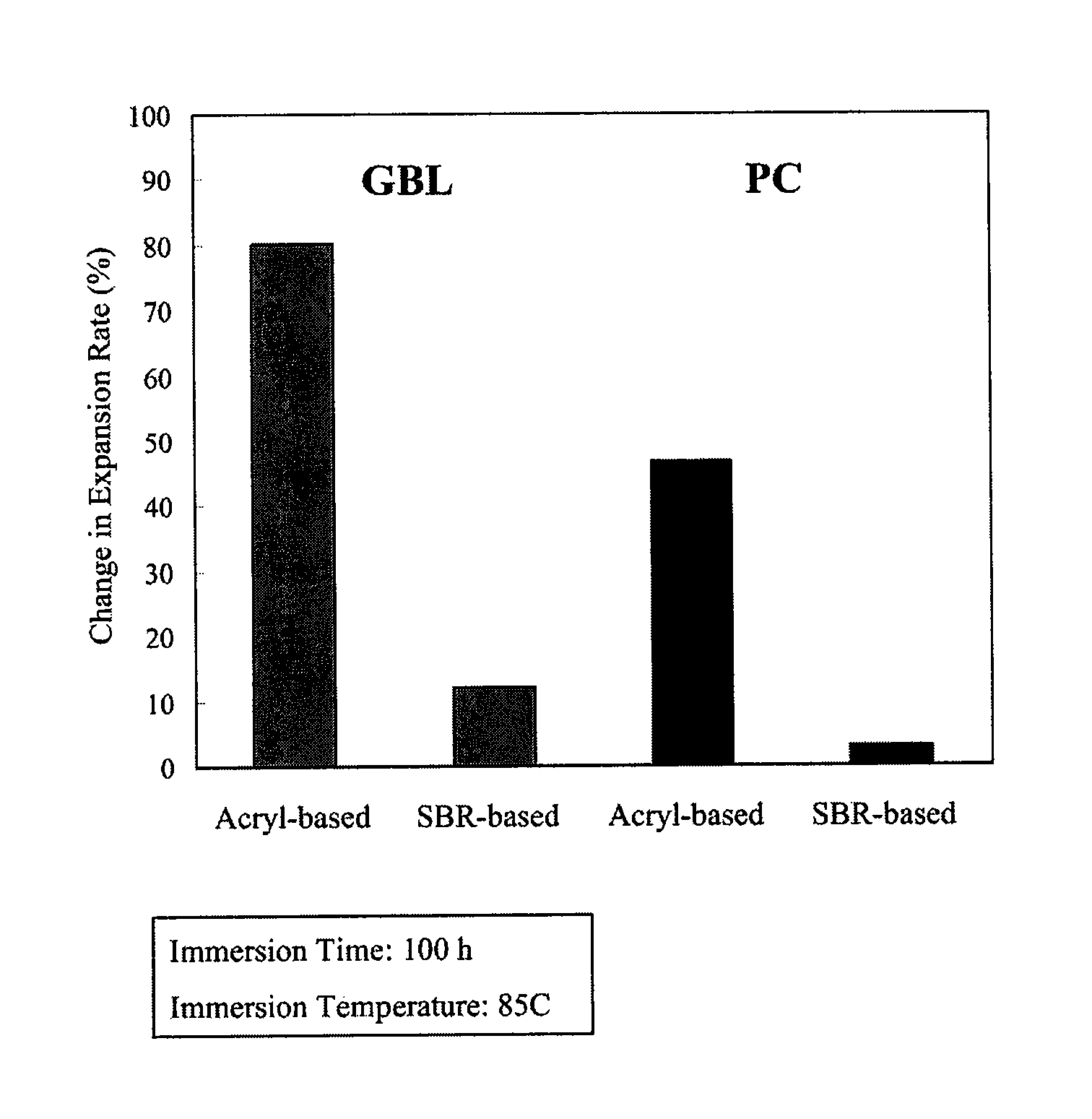
[0035]Activated carbon 4 as the base material, and ketjen black (KB) as the electrically conductive auxiliary agent are added to this, and high shear is provided by a mixer 3 of the stirring machine 1 for dispersion. Further, styrene butadiene rubber having an expansion rate of 13% in γ-butyrolactone (S2904(C)-1 from JSR) is added as the binding agent, and these are mixed to prepare a slurry. The target viscosity at this time is 3000-7000 mPa·s (FIG. 1 (B)).

[0036]Next, the prepared slurry is coated on an aluminum etching foil 6 with a coating machine 5 to prepare a coated electrode 7, and a leading-out terminal are set up on this to prepare an electrode for electric double-laye...


PUM

PropertyMeasurementUnit
temperatureaaaaaaaaaa
diameteraaaaaaaaaa
temperatureaaaaaaaaaa

Abstract

The electric double-layer capacitor of the present invention comprises an electrolyte solution comprising γ-butyrolactone as the solvent and a coated electrode. The coated electrode is produced by using water as the solvent, and prepared by coating a slurry onto a current collector, wherein the slurry consists of an electrode material which is the solute, an electrically conductive auxiliary agent, and an elastomer having an expansion rate of 50% or less in γ-butyrolactone at 85° C. after 100 hours as the binding agent. For example, a styrene-butadiene elastomer is employed as the elastomer. Because expansion rate in γ-butyrolactone is low, deterioration of internal resistance does not occur. Styrene-butadiene elastomer is easy to handle since water can be used as the solvent for the slurry.

Description

TECHNICAL FIELD[0001]The present invention relates to an electric double-layer capacitor that uses a coated electrode formed by coating a slurry electrode onto a current collector. The present invention also relates to a current collector for electric double-layer capacitor and an electric double-layer capacitor that prevents deterioration of properties even at a temperature range of approximately 85° C.BACKGROUND ART[0002]The electric double-layer capacitor has a structure where a capacitor element impregnated with an electrolyte solution is housed in a metal case and open ends thereof are sealed. The capacitor element is formed by winding or laminating polarized electrodes, which is prepared by providing a polarized electrode layer on the surface of a metal foil such as aluminum, with a separator interpositioned in between.[0003]This electric double-layer capacitor attempts improvement of power density by reducing the thickness of the electrode in applications of power supply for ...

Claims


Application Information

Patent Timeline
Patent Type & Authority Patents(United States)
IPC IPC(8): H01G9/00H01G9/145H01G11/28H01G11/60H01G11/62H01G11/38H01M6/04H01G9/02H01G9/04H01G11/86H01G11/68H01G11/26
CPCH01G11/28H01G11/38H01G11/60H01G11/62H01G11/68H01G11/86Y02E60/13Y02T10/7022Y02T10/70
Inventor HAGIYA, MASAYUKIKOMATSU, HIROSHI
Owner NIPPON CHIMI CON CORP
Why Eureka
Try Eureka