Charging circuit and method for preventing charging power supply from reversely connecting
a charging circuit and power supply technology, applied in safety/protection circuits, relays, transportation and packaging, etc., can solve the problems of no uniform criterion for adapters, damage to charging circuits and batteries, and face risks, so as to prevent the risk of electronic cigarettes or electronic cigarette cases, low voltage drop, and low power consumption
- Summary
- Abstract
- Description
- Claims
- Application Information
AI Technical Summary
Benefits of technology
Problems solved by technology
Method used
Image
Examples
first embodiment
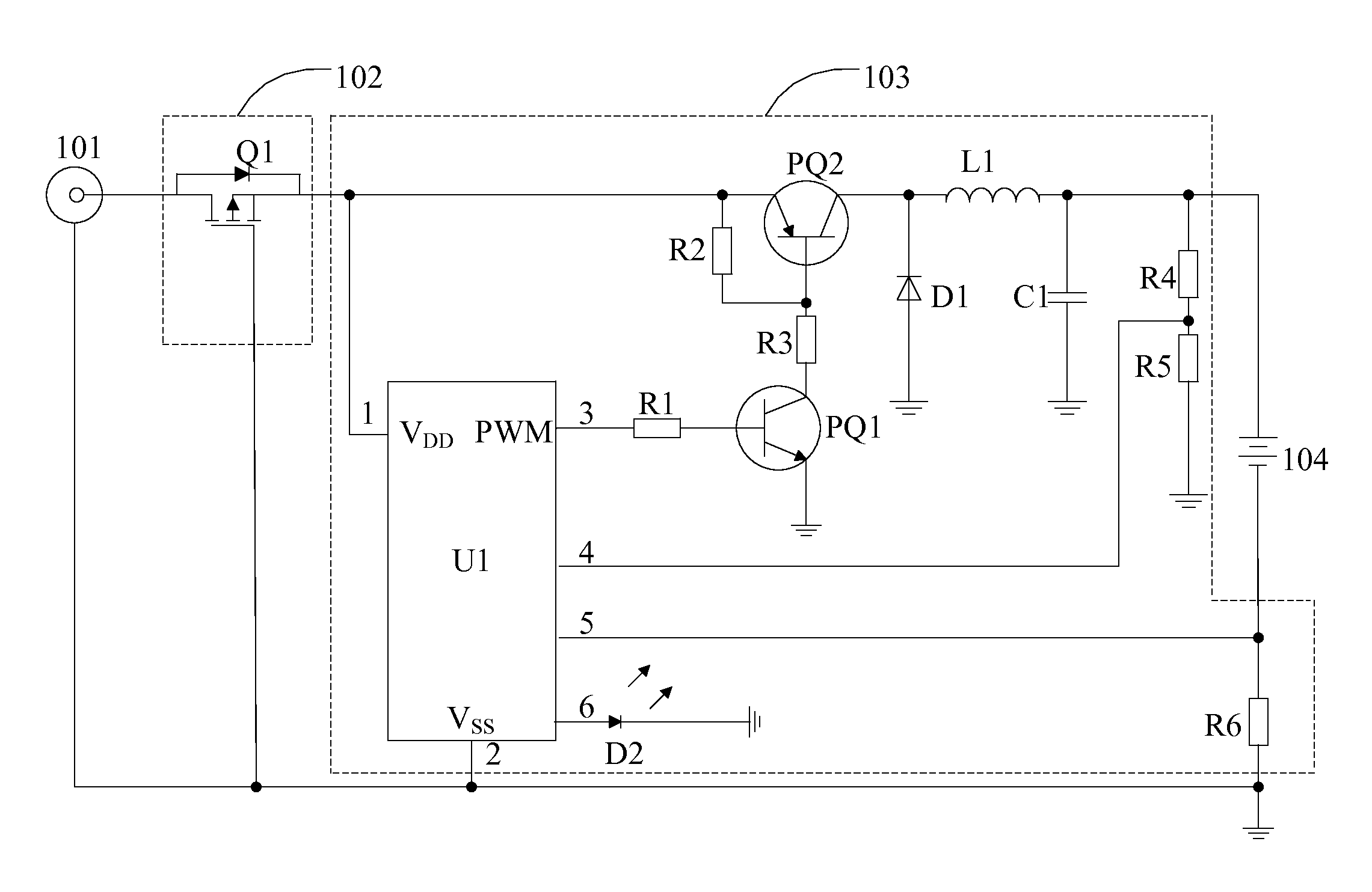
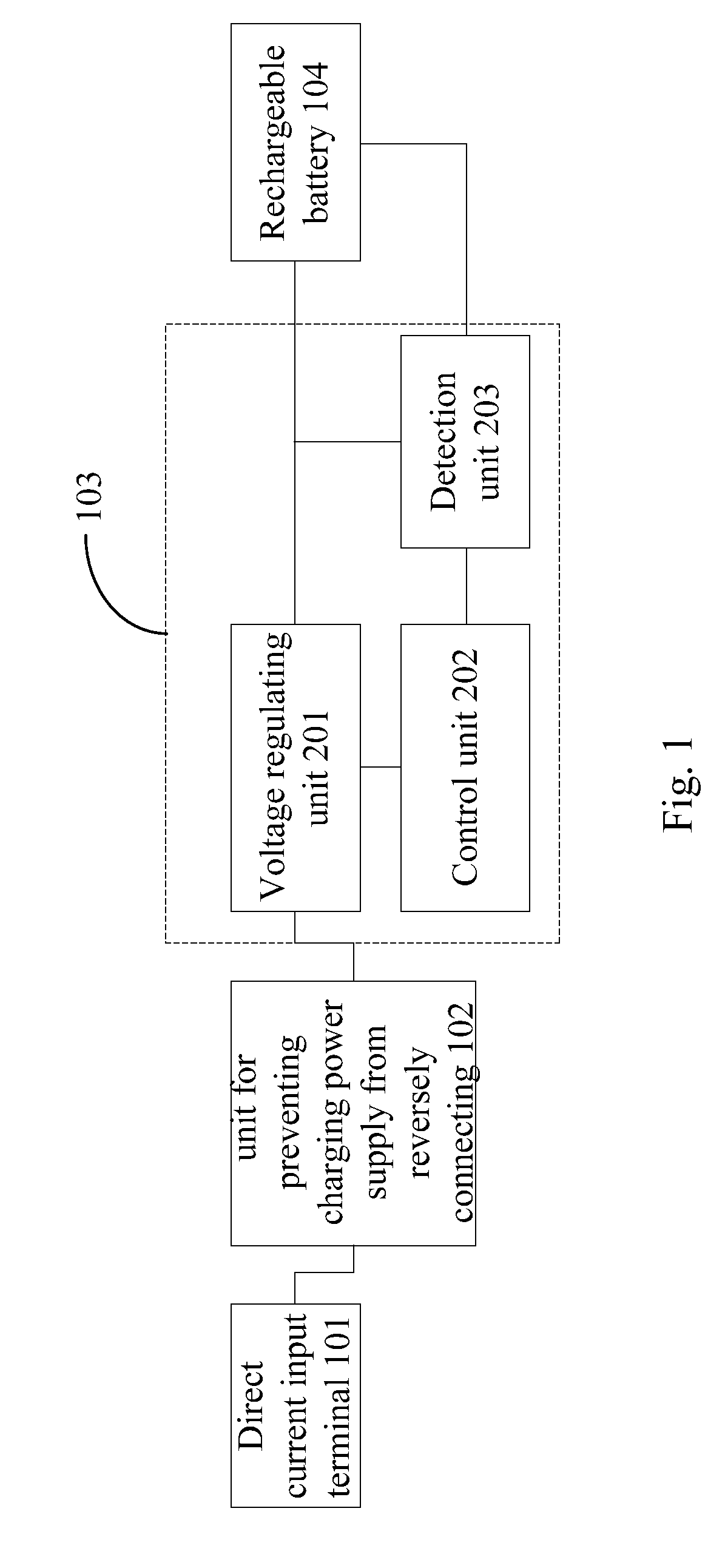
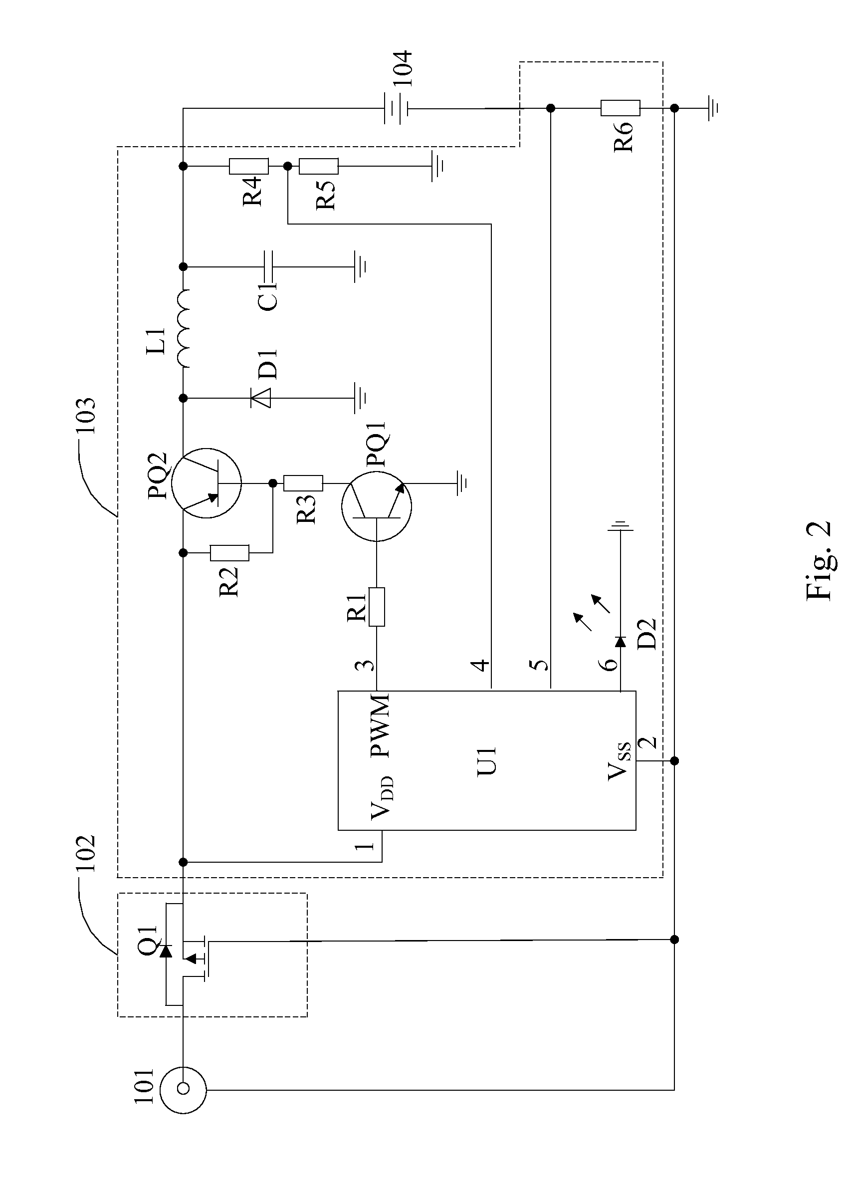
[0067]As shown in FIG. 2, it is a circuit diagram of a circuit for preventing charging power supply from reversely connecting according to the present invention. The charging circuit for preventing charging power supply from reversely connecting includes the direct current input terminal 101, the unit for preventing charging power supply from reversely connecting 102, the charge management unit 103 and the rechargeable battery 104. Wherein the unit for preventing charging power supply from reversely connecting 102 includes a MOSFET Q1 that is a P channel MOSFET. For example, a AO3401 MOSFET may be chosen as the MOSFET Q1. The control unit of the charge management unit 103 includes a microcontroller U1. Wherein the microcontroller U1 comprises a VDD terminal 1, a VSS terminal 2, a pulse signal output terminal 3, a first input terminal 4 and a second input terminal 5. The voltage regulating unit includes a first triode PQ1, a second triode PQ2, a first resistance R1, a second resistan...
second embodiment
[0079]In the second embodiment, the reminding circuit for reversal connection 105 includes a light emitting diode D3, current limiting resistance R7 and a first diode D4 and a buzzer H1.
[0080]Reference to FIG. 4, the cathode of the light emitting diode D3 is connected to the anode of the direct current input terminal 101, and the anode thereof is connected to the cathode of the first diode D4 through the current limiting resistance R7. Wherein the anode of the first diode D4 is connected to the cathode of the direct current input terminal 101. One end of the buzzer H1 is connected to one end of the current limiting resistance R7 and the cathode of the first diode D4, the other end thereof is connected to the anode of the direct current input terminal 101 and the cathode of the light emitting diode D3.
[0081]In the second embodiment, when the outer charging power supply is connected normally, a diode D4 is cutoff and the light emitting diode D3 and the buzzer H1 stop working. When the...
third embodiment
[0084]As shown in FIG. 5, in the invention, the unit for preventing charging power supply from reversely connecting 102 includes a MOSFET Q2. The MOSFET Q2 is a N channel MOSFET. For example, a AO3402 MOSFET may be chosen as the MOSFET Q1.
[0085]Wherein the drain of the MOSFET Q2 is connected to the cathode of the direct current input terminal 101. The source of the MOSFET Q2 is connected to the cathode of the rechargeable battery 104 through the sixth resistance R6. The gate of the second MOSFET Q2 is connected to the anode of the direct current input terminal 101 as well as the charge management unit 103.
[0086]Reference to FIG. 5, in the third embodiment of the invention, the control unit of the charge management 103 includes a microcontroller U1. wherein the microcontroller U1 comprises a VDD terminal 1, a VSS terminal 2, a pulse signal output terminal 3, a first input terminal 4 and a second input terminal 5. wherein, the voltage regulating unit 201 includes a first triode PQ1, a...
PUM
 Abstract
Description
Claims
Application Information
 - R&D
- Intellectual Property
- Life Sciences
- Materials
- Tech Scout
- Unparalleled Data Quality
- Higher Quality Content
- 60% Fewer Hallucinations
Browse by: Latest US Patents, China's latest patents, Technical Efficacy Thesaurus, Application Domain, Technology Topic, Popular Technical Reports.
© 2025 PatSnap. All rights reserved.Legal|Privacy policy|Modern Slavery Act Transparency Statement|Sitemap|About US| Contact US: help@patsnap.com


