Electrohydraulic hybrid work vehicle

a hybrid work and electric motor technology, applied in the field of hybrid work vehicles, can solve the problems of affecting the reliability of the vehicle, affecting the overall vehicle control, and being fairly complicated mechanically and in terms of vehicle control, and achieve the effect of high performance and convenient and cheap us

Active Publication Date: 2016-02-02
MERLO PROJECT SRL CON UNICO SOCIO
View PDF19 Cites 13 Cited by
  • Summary
  • Abstract
  • Description
  • Claims
  • Application Information

AI Technical Summary

Benefits of technology

[0029]The present invention aims at providing an improved configuration by which to convert work and / or telescopic-arm lift vehicles to hybrid, electric-drive vehicles easily and cheaply in terms of component part assembly cost, while at the same time maintaining high performance.
[0030]The aims of the present invention are achieved at least by a work vehicle as claimed in claim 1. More specifically, the hybrid assembly according to the invention operates in series to drive the vehicle, and in parallel to operate the hydraulic systems. With this solution, the internal combustion engine, hydraulic pump, and hydraulic pump motor / generator can be housed in the conventional engine compartment of the vehicle, and the electric vehicle drive motor / s can be located according to the architecture of the work vehicle, i.e. with no need for complex, high-cost vehicle gear drives.

Problems solved by technology

The high voltage and amperage of the electric power components may interfere with the low-voltage electric circuit signals, thus impairing reliability of the vehicle and, in particular, altering the control signal from the user or the central control unit and so resulting in uncommanded, unpredictable operation of the vehicle
US2005061564 describes a parallel, input-split / output-split layout, which has the drawback of being fairly complicated mechanically and in terms of overall vehicle control.
Especially in the case of hybrid work vehicles involving high power levels, the hydraulic system, which normally demands more or less the same amount of power as for driving the vehicle, would further complicate the drive, the configuration of which is thus less than optimum.
This is a particularly bulky configuration, which, by raising the centre of gravity, is unsuitable for telescopic-arm vehicles, which, for reasons of stability, have to maintain a low centre of gravity to avoid rolling over.
Moreover, no mention is made of the problems involved in assembling individual components to minimize the impact on the layout of a telescopic-arm vehicle.
Which means the user can also act on the speed of the internal combustion engine on the basis of the load demanded of the electric motor, at the expense of the energy efficiency of the vehicle as a whole.
This greatly affects the size of hybrid excavator battery packs.
The excavator described therefore cannot be run fully electrically to simultaneously drive the vehicle and operate the shovel.
On the contrary, the internal combustion engine must be run continuously to simultaneously operate the hydraulic system and drive the vehicle; and the hydraulic system can only be powered electrically when the vehicle is stationary.

Method used


Image

  • Electrohydraulic hybrid work vehicle
  • Electrohydraulic hybrid work vehicle
  • Electrohydraulic hybrid work vehicle

Examples


Embodiment Construction

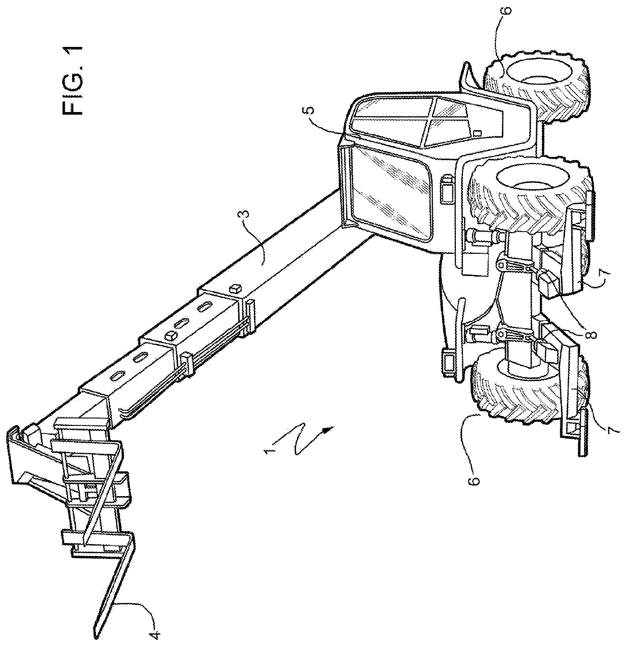
[0038]Number 1 in FIG. 1 indicates as a whole a lift vehicle comprising a frame; a preferably telescopic arm 3 hinged to the frame; a fork 4 fitted to a free end portion of arm 3; a drive cab 5; wheels 6 on two axles; and front and rear stabilizer arms 7 (only the front arms shown in FIG. 1). Front and rear stabilizer arms 7 are operated by respective hydraulic cylinders 8, and are movable between an up position, in which wheels 6 rest on the ground, allowing vehicle 1 to move; and a down position, into which they are lowered by hydraulic cylinders 8 and rest on the ground on plates 9.

[0039]Hydraulic cylinders 8 are designed to raise even the fully loaded vehicle 1, and so raise wheels 6 off the ground at the discretion of the operator in cab 5, so arm 3 can be operated with wheels 6 resting on the ground and stabilizer arms 7 in the up position, or with stabilizer arms 7 in the down position and wheels 6 raised.

[0040]The lift angle of arm 3 with respect to a plane through the axles...


PUM


Abstract

A hybrid work vehicle having a direct-current electric power bus for connecting at least an electric power controller, an electric machine for driving the vehicle, a reversible electric machine, and a battery.

Description

RELATED APPLICATION DATA[0001]This application is the national stage entry of International Appl. No. PCT / IB2012 / 055608, filed Oct. 15, 2012, which claims priority to Italian Patent Application No. TO2011A000924, filed on Oct. 14, 2011. All claims of priority to these applications are hereby made, and each of these applications is hereby incorporated in its entirety by reference.TECHNICAL FIELD[0002]The present invention relates to a hybrid work, construction or farm vehicle, such as a lift vehicle with a front or swivel telescopic arm.BACKGROUND ART[0003]A hybrid vehicle has electric power components, such as motors, alternators, electric actuators and batteries, powered by high-voltage, high-amp alternating or direct current; and a low-voltage / low-amp electric circuit for controlling the electric power components and any other controls or servocontrols.[0004]The high voltage and amperage of the electric power components may interfere with the low-voltage electric circuit signals, ...

Claims


Application Information

Patent Timeline
Patent Type & Authority Patents(United States)
IPC IPC(8): B60K6/26B60K6/46E02F9/20B60K25/00B60W10/30B60W20/00H02K11/00B60K1/00B60K25/02B66F9/065
CPCB60K6/46B60K6/26B60K25/00B60W10/30B60W20/00B66F9/0655E02F9/2075H02K11/01B60K2001/003B60K2025/005B60K2025/022B60Y2200/64B60Y2400/61B60Y2410/115Y02T10/6217Y10S903/903H02K11/33H02K11/0141Y02T10/62B60W10/26
Inventor SOMA', AURELIOGALFRE', RENATOMERLO, AMILCARE
Owner MERLO PROJECT SRL CON UNICO SOCIO
Why Eureka
Try Eureka