Transmission for working vehicle

a technology for working vehicles and transmissions, applied in the direction of non-deflectible wheel steering, transportation and packaging, and mounting of jet propulsion, etc., can solve the problems of labor and space for the piping of pipes, and it is difficult to arrange this type of transmissions in the space, so as to reduce the height difference

Active Publication Date: 2016-02-02
KANZAKI KOKYUKOKI MFG
View PDF10 Cites 14 Cited by
  • Summary
  • Abstract
  • Description
  • Claims
  • Application Information

AI Technical Summary

Benefits of technology

[0011]Therefore, the transmission including the input shaft for receiving power from the engine, the output shaft for outputting power to the pair of transaxles, and the PTO shaft for outputting power to the working device, also includes the axial end of the input shaft serving as the joint, and the universal joint on the PTO shaft, thereby facilitating coupling of the flywheel of the engine to the input shaft, coupling of the output shafts to the pair of transaxles, and coupling of the PTO shaft to the working device, whereby a power train from the horizontal engine having the horizontal output shaft to the pair of transaxles and the working device can be easily configured in the working vehicle. Further, due to the horizontal input shaft corresponding to the engine output shaft, and the horizontal PTO shaft parallel to the input shaft, a propeller shaft and another universal joint can be easily used to couple the universal joint on the PTO shaft to an input shaft of the working device if the working device, e.g., a mower unit, has the input shaft extended horizontally.
[0013]Therefore, the side end of the casing can easily be joined to the engine, so that the transmission can easily be mounted onto the engine when the input shaft is coupled to the flywheel.
[0015]Therefore, due to the gear ratio of the first gear train such as to substantially equalize the rotary speed of the output shaft to the rotary speed of the input shaft, the output shaft of the transmission can be rotated at a considerably high speed so as to input rotary power to the transaxles for rotating drive wheels at an appropriate speed. On the other hand, due to the gear ratio of the second gear train such as to make the rotary speed of the PTO shaft less than the rotary speed of the input shaft, i.e., since the second gear train is a reduction gear train, the working device can receive an appropriate input rotary power from the PTO shaft with a high torque at a low speed suitable for work by the working device.
[0019]Therefore, due to the vertical output shaft, a belt and pulleys can easily be used to drivingly connect the output shaft to input shafts of the transaxles if the input shafts of the transaxles are vertical. Further, due to the extended portion of the casing, the height of the PTO shaft becomes appropriate for its driving connection to the working device if the working device, e.g., a mower unit, has an input shaft at a considerably low position. Ifa propeller shaft and another universal joint are used to drivingly connect the PTO shaft to the input shaft of the working device, an angle of the propeller shaft relative to the PTO shaft and the input shaft of the working device can be small so as to enhance the power transmission efficiency. Further, due to the extended portion of the casing, a space below the casing can be expanded along the extended portion of the casing so that the vertical output shaft can project downward from the casing into the space below the casing, and a belt and pulleys can be disposed in this space to drivingly connect the output shaft to the transaxles.
[0021]Therefore, due to the pair of horizontal output shafts extended laterally of the working vehicle and projecting laterally outward from right and left ends of the casing, splined sleeves, for example, can easily be used to drivingly connect the output shafts of the transmission to input shafts of the transaxles if the input shafts of the transaxles are horizontal and coaxial to the output shafts of the transmission. Further, due to the first gear train including the first bevel gear fixed on the input shaft of the transmission and the second bevel gears fixed on the respective output shafts and meshing with the first bevel gear, component members of the first gear train is reduced in number so as to minimize the entire first gear train, and the minimized first gear train reduces a difference in height between the input shaft of the transmission and the output shafts of the transmission. Further, while the input shafts of the transaxles are connected to the respective output shafts of the transmission coaxial to the input shafts of the transaxles, location of the first bevel gear on the input shaft in the fore-and-aft direction directly leads to location of the second bevel gears on the output shafts in the fore-and-aft direction so as to determine the fore-and-aft, whereby the transmission and the transaxles can be joined together with small gaps, i.e., a compact power transmission assembly including the transmission and the transaxles can be configured.

Problems solved by technology

If a vehicle has a narrowed space close to the engine, it is hard to arrange this type of transmission in the space.
Piping of the pipes needs labor and space.
This distribution of the hydraulic pumps between the transaxles will make the pipes unnecessary and will make the transmission compact.

Method used


Image

  • Transmission for working vehicle
  • Transmission for working vehicle
  • Transmission for working vehicle

Examples


Embodiment Construction

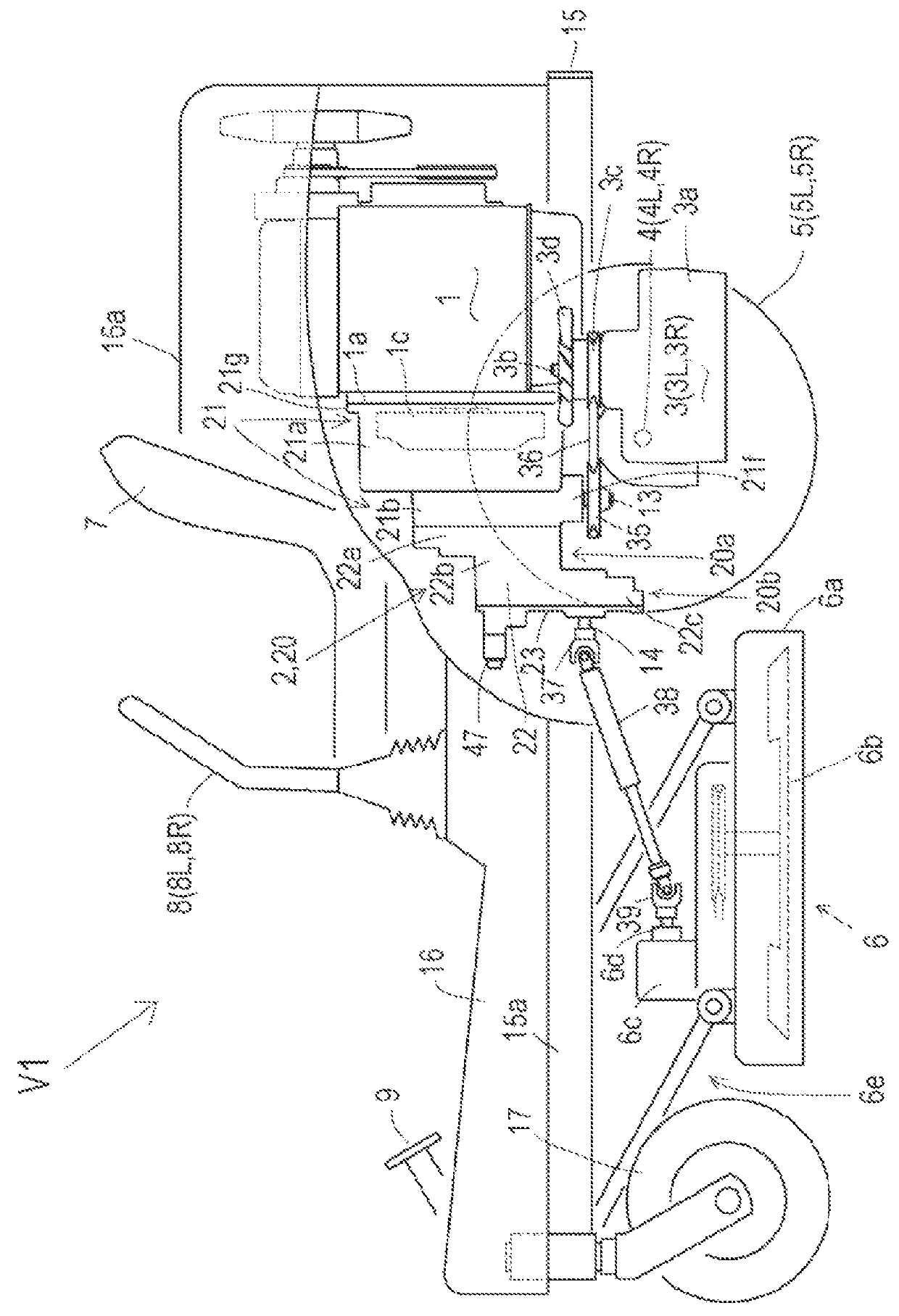
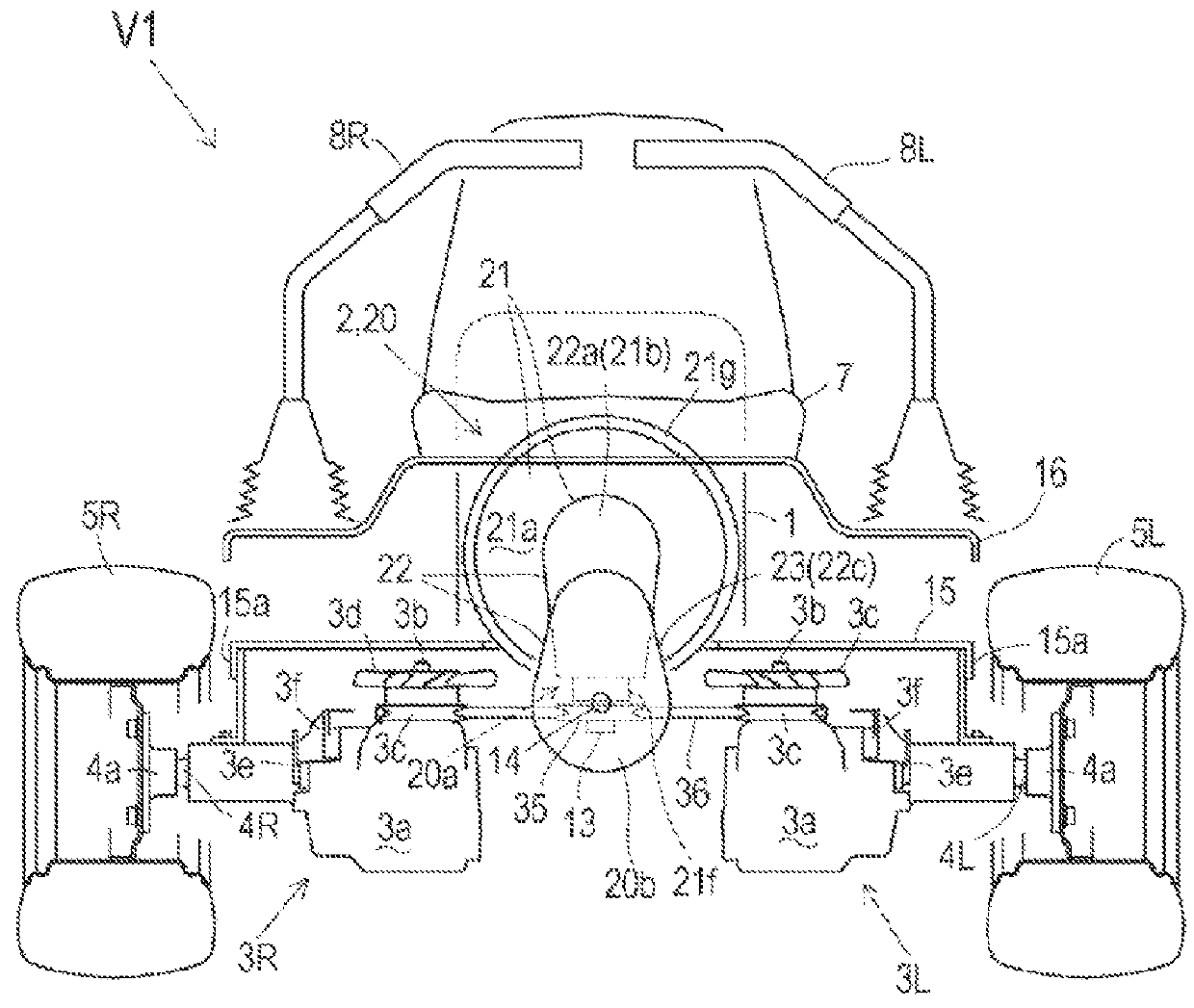
[0034]An embodiment shown in FIGS. 1 to 3 will be described. FIGS. 1 and 2 illustrate a mower tractor (hereinafter referred to as “vehicle”) V1 serving as an embodiment of a zero-turn working vehicle equipped with an engine having a fore-and-aft horizontal engine output shaft. A general structure of vehicle V1 will be described with reference to FIGS. 1 and 2. Vehicle V1 includes a vehicle body frame 15 extended from a front end thereof to a rear end thereof. Castors 17 serving as front wheels of vehicle V1 are carried at a front end of vehicle body frame 15. An upper portion of vehicle body frame 15 is covered with a vehicle body cover 16. An operator's seat 7 is mounted at a fore-and-aft center portion of vehicle V1 above vehicle body cover 16. Right and left control levers 8R and 8L, generally referred to as “control levers 8”, are disposed at right and left sides of seat 7. A brake pedal 9 is disposed forward from seat 7.

[0035]A portion of vehicle body cover 16 rearward from sea...


PUM


Abstract

A transmission for a working vehicle equipped with an engine having a horizontal engine output shaft, pair of transaxles for driving right and left drive wheels at variable speeds, and working device comprises a horizontal input shaft, output shaft, first gear train, horizontal PTO shaft, second gear train, PTO clutch and casing. An axial end of the input shaft connects to a flywheel of the engine. The output shaft drivingly connects to the transaxles. The first gear train transmits power from the input shaft to the output shaft. The PTO shaft extends parallel to the input shaft, and is provided with a universal joint connected to the working device. The second gear train transmits power from the input shaft to the PTO shaft via the PTO clutch. The casing supports the input and output shafts and incorporates the first and second gear trains and the PTO clutch.

Description

CROSS-REFERENCE TO RELATED APPLICATIONS[0001]The present application claims priority to Japanese Patent Applications No. 2014-032303, filed on Feb. 21, 2014, and No. 2014-111684, filed on May 29, 2014.BACKGROUND OF THE INVENTION[0002]1. Field of the Invention[0003]The present invention relates to a transmission adapted for a working vehicle, which is equipped with an engine (referred to as a “horizontal engine”) having a horizontal output shaft, a pair of transaxles for driving respective right and left drive wheels, and a working device.[0004]2. Related Art[0005]There is a well-known conventional vehicle, referred to as a “zero-turn vehicle”, which is equipped with right and left transaxles carrying respective right and left axles so as to individually drive the respective axles. US 2003 / 0188909 A discloses a mower tractor (riding lawn mower) as one of such zero-turn vehicles. This mower tractor is equipped with an engine having a horizontal engine output shaft, and a transmission ...

Claims


Application Information

Patent Timeline
Patent Type & Authority Patents(United States)
IPC IPC(8): B60K25/08B60K17/28B60K5/02B60K17/10B62D11/04B60K17/04
CPCB60K17/04B60K5/02B60K17/105B60K17/28B62D11/04B60Y2200/223A01D34/64A01D69/06
Inventor IWAKI, KOJIIMA, AKIHIROYASUDA, TOSHIFUMI
Owner KANZAKI KOKYUKOKI MFG
Why Eureka
Try Eureka