Supercharge Your Innovation With Domain-Expert AI Agents!

Transistor gate driver with charge pump circuit for offline power converters

a technology of transformer gate driver and power converter, which is applied in the direction of process and machine control, pulse technique, instruments, etc., can solve the problems of large die size and higher cost of the controller circuit, and achieve the effect of reducing cost and circuit siz

Active Publication Date: 2016-02-02
SEMICON COMPONENTS IND LLC
View PDF8 Cites 0 Cited by
  • Summary
  • Abstract
  • Description
  • Claims
  • Application Information

AI Technical Summary

Benefits of technology

The objective of this patent is to create a gate driver for power converters that includes a charge-pump circuit for a controller. The goal is to reduce the cost and size of the circuit's controller.

Problems solved by technology

A prior art “Transistor drive circuit of power converter operating in a wide voltage range”, U.S. Pat. No. 7,471,121 was designed to solve this problem, but its drawbacks are bigger die size and the higher cost of the circuit of the controller.

Method used


Image

  • Transistor gate driver with charge pump circuit for offline power converters
  • Transistor gate driver with charge pump circuit for offline power converters
  • Transistor gate driver with charge pump circuit for offline power converters

Examples


Embodiment Construction

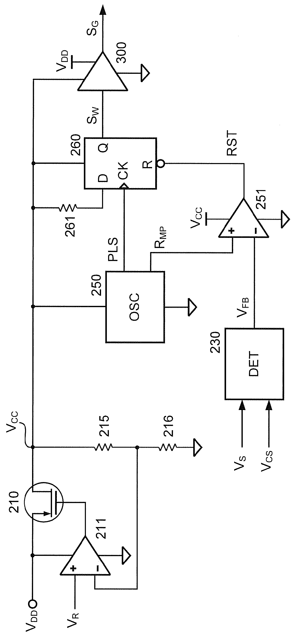
[0026]FIG. 3 is a circuit schematic of an embodiment of a controller according to the present invention. The controller 100 replaces the controller 50 shown in FIG. 1. The source voltage VDD is coupled to a source of a transistor 210 and an error amplifier 211. A drain of the transistor 210 is coupled to a voltage divider. In this embodiment, the transistor 210 is the PMOS type. The voltage divider includes resistors 215 and 216. A first terminal of the resistor 215 is coupled to the drain of the transistor 210. The resistor 216 is coupled between a second terminal of the resistor 215 and the ground. A positive input terminal of the error amplifier 211 is coupled to receive a reference signal VR. A negative input terminal of the error amplifier 211 is coupled to a join of the resistors 215 and 216. An output terminal of the error amplifier 211 is coupled to a gate of the transistor 210.

[0027]The source voltage VDD could be a various voltage, such as 5V to 25V. Thus, the transistor 2...


PUM


Abstract

A controller of the power converter according to the present invention comprises a gate driver. The gate driver generates a gate-drive signal. The gate-drive signal is coupled to drive a power transistor to switch a transformer of the power converter for regulating an output of the power converter. The gate driver has a charge-pump circuit for charging pump a voltage level of the gate-drive signal. Therefore, the gate-drive signal can fully turn on the power transistor.

Description

BACKGROUND OF THE INVENTION[0001]1. Field of Invention[0002]The present invention relates to a power converter, and more particularly, the present invention relates to a transistor gate driver with a charge-pump circuit of a controller for the power converter.[0003]2. Description of Related Art[0004]FIG. 1 shows a circuit diagram of a primary side regulated power converter with the constant current output. The power converter (such as a power adaptor) is required to charge a battery with a constant current. The power converter includes a transformer 110 for generating an output (an output voltage VO and an output current IO). The transformer 110 has a primary winding NP, a secondary winding NS, and an auxiliary winding NA. The secondary winding NS generates the output voltage VO and the output current IO through a diode 140 and a capacitor 145. The output voltage VO and the output current IO are generated at an output terminal of the power converter. A first terminal of the primary ...

Claims


Application Information

Patent Timeline
Patent Type & Authority Patents(United States)
IPC IPC(8): H02M3/335H03K17/06
CPCH03K17/063H02M3/33523
Inventor YANG, TA-YUNGLIN, CHIN-YENCHEN, JUNG-SHENGLIN, LI
Owner SEMICON COMPONENTS IND LLC
Features
  • R&D
  • Intellectual Property
  • Life Sciences
  • Materials
  • Tech Scout
  • Unparalleled Data Quality
  • Higher Quality Content
  • 60% Fewer Hallucinations
Learn More