Cooling device with liquid for electronic cards, in particular for high performance processing units

a technology of electronic cards and liquid cooling, which is applied in the direction of cooling/ventilation/heating modifications, electrical equipment, electrical apparatus contruction details, etc., can solve the problems of reducing the service life of electronic cards, reducing the possibility of maintenance interventions, and not allowing efficient removal of heat produced, so as to reduce the possibility of electronic components breaking, increase mechanical rigidity and stability, and absorb mechanical tension and stress

Active Publication Date: 2016-02-02
EUROTECH
View PDF22 Cites 3 Cited by
  • Summary
  • Abstract
  • Description
  • Claims
  • Application Information

AI Technical Summary

Benefits of technology

[0021]Thanks to the sliding guide means it is possible to prevent the mechanical interferences of the known state of the art between adjacent electronic cards, due to the bulk of the circuit itself. Moreover, it is not difficult to extract the electronic card for maintenance needs, together with the cooling plate, from a corresponding containing rack, as it is for cooling devices with liquid in the state of the art, and the extraction is substantially facilitated by the sliding guides. Moreover, as the guides are directly integrated in the plate, it is possible to reduce, to a considerable extent, the possible breakages of the electronic card, given that, during the extraction / insertion operations, the electronic card is not physically touched.
[0026]Therefore the cooling device with liquid according to the present invention allows to selectively convey a desired amount of heat-carrying fluid depending on the effective circuital or topological configuration of the associated electronic card, toward specific electronic components. Moreover, given that the heat extraction surface is directly in contact with the electronic components and with the hot spots of the electronic card, it is possible to carry out a very efficient heat exchange. In turn this allows to maintain the temperature of the electronic components within optimal functioning ranges, typically the suggested operating ranges, allowing a substantial reduction in electric consumption, and increasing their working life.
[0028]Therefore the cooling device according to the present invention also allows, as a further connected advantage, to increase the mechanical rigidity and stability of the electronic card and to absorb possible mechanical tensions and stresses. Indeed, electronic cards for high-performance processing units usually have considerable longitudinal sizes and are subjected, when they are inserted into the rack, to considerable mechanical stresses in a longitudinal direction in order to determine the mechanical coupling between the relative electric connectors in the rack. Moreover, given that the cooling plate is stably disposed, during use, above and directly in contact with the components to be cooled, it acts as a protection element, considerably reducing the possibility of breakage of the electronic components during normal maintenance operations.

Problems solved by technology

Moreover, by restricting the functioning temperature range of the electronic cards by cooling them, it is possible to increase the working life of their components, at the same time reducing possible maintenance interventions.
Air cooling, that is, using a stream of forced air which is conveyed above the electronic components that produce most heat, and which is subsequently extracted from inside the container or rack of the electronic cards by means of one or more fans, does not allow an efficient removal of the heat produced, especially when there is a high density of electronic integration of the components on the cards.
Moreover, the presence of continuously moving mechanical components, such as the fans, entails the need for periodic diagnostic controls and / or maintenance in order to verify their correct functioning or to remove possible residues of impurities, such as powders or other, which can compromise the proper functioning.
Such systems are also noisy and, if there are a large number of fans, they can make the work environment uncomfortable.
One drawback of this cooling technique with liquid is that, in the case of high integration of the electronic components and of high density of the hot spots, the spaces for the movement of the hot air inside the container or rack can be reduced quite considerably, and may even obstruct the desired movement of hot air toward the points provided for heat exchange on the pipe, rendering the extraction of heat inefficient and increasing the electric consumption of the processing units.
However, one drawback of this solution is the constraints and the mechanical interferences due to the conformation and development of the pipe inside the container or rack, in which the electronic cards are housed.
This, in its turn, makes it very difficult to remove the electronic cards from the container or rack, in practice increasing the times and the maintenance costs.
The cooling plates have a transverse thickness, which together with the thickness of the electronic cards themselves, makes it difficult to insert them inside the containing racks of the processing units.
Moreover, the extraction of the heat is not very efficient, given that the heat-carrying fluid is hotter toward the exit from the hydraulic circuit, thus determining an inefficient cooling of some electronic components or of the relative hot spots, or requiring an over-sizing of the hydraulic circuits themselves.
This solution, because it requires a separate support element, is not very efficient, it is bulky, it cannot have any shape whatsoever, it is not adaptable to any PCB configuration, it requires a precise assemblage sequence, there are maintenance problems and still other drawbacks.

Method used


Image

  • Cooling device with liquid for electronic cards, in particular for high performance processing units
  • Cooling device with liquid for electronic cards, in particular for high performance processing units
  • Cooling device with liquid for electronic cards, in particular for high performance processing units

Examples


Embodiment Construction

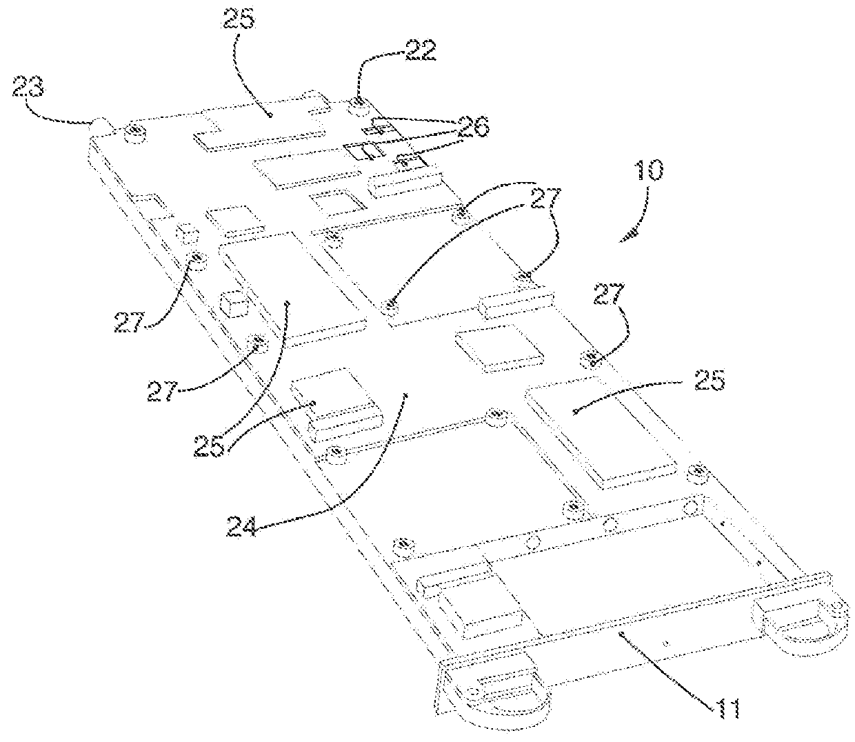
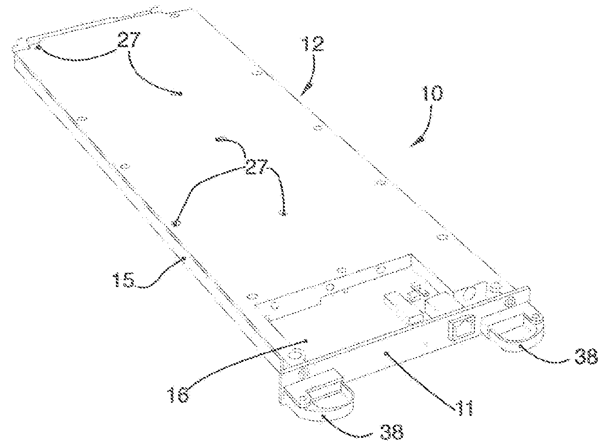
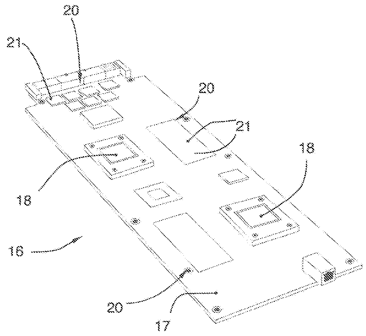
[0053]With reference to the attached drawings, a cooling device 10 with liquid for electronic cards according to the present invention can be used, preferably but not exclusively, in high-performance processing units such as supercomputers. In particular the cooling device 10 with liquid according to the present invention allows to increase the mechanical stability of the electronic cards and to speed up maintenance operations, such as the extraction or substitution or hot swap of electronic cards, or compute nodes of said supercomputers. It is understood that the device 10 according to the present invention can also be used for cooling graphic processing cards, control cards or other cards also used in processing units such as the work station or others.

[0054]As shown in the drawings, the device 10 is applied to electronic processing cards 16 of a high capacity processing unit 40 (FIG. 12) or supercomputer, which has one or more containing racks 30 into which the cards 16 are inser...


PUM


Abstract

Cooling device with liquid for electronic cards, in particular for high-performance processing units, comprising at least a hydraulic circuit in which a heat-carrying fluid flows in order to extract the heat produced by electronic components and / or hot spots present on an associated electronic card. The device comprises a cooling plate mechanically coupled to the electronic card so as to be inserted in a containing rack of the processing unit. The plate has a heat extraction surface facing and partly in contact, or at least in close proximity, with the electronic components and / or the hot spots. The hydraulic circuit is made in the thickness of the plate and has a geometric grid development, along which a plurality of hydraulic sub-circuits are disposed and switching means to define desired paths. The plate has sliding guide means able to cooperate with corresponding alignment means of the containing rack.

Description

FIELD OF THE INVENTION[0001]The present invention concerns a cooling device with liquid for electronic cards, in particular for high-performance processing units.BACKGROUND OF THE INVENTION[0002]In the field of high-performance processing units or “supercomputers” it is known to cool the electronic cards, and in particular the electronic components mounted on them, such as integrated circuits, microprocessors and others, in order to prevent the limit values of functioning temperature from being exceeded, above which irreversible damage can be caused. Moreover, by restricting the functioning temperature range of the electronic cards by cooling them, it is possible to increase the working life of their components, at the same time reducing possible maintenance interventions.[0003]Air cooling, that is, using a stream of forced air which is conveyed above the electronic components that produce most heat, and which is subsequently extracted from inside the container or rack of the electr...

Claims


Application Information

Patent Timeline
Patent Type & Authority Patents(United States)
IPC IPC(8): H05K7/20
CPCH05K7/20254H05K7/20636H05K7/20772
Inventor ROSSI, MAUROTECCHIOLLI, GIAMPIETROZUCCATO, PIERFRANCESCO
Owner EUROTECH
Why Eureka
Try Eureka