Low cost charger circuit with precharge

a charger circuit and low-cost technology, applied in the direction of charging stations, electric devices, transportation and packaging, etc., can solve the problems of reducing adding loads that reduce the reducing the overall safety and efficiency of the charging process, so as to limit or prevent unnecessary energizing of the dc/dc converter and improving the overall safety and efficiency. , the effect of avoiding damage to its components

Active Publication Date: 2016-02-23
FORD GLOBAL TECH LLC
View PDF9 Cites 4 Cited by
  • Summary
  • Abstract
  • Description
  • Claims
  • Application Information

AI Technical Summary

Benefits of technology

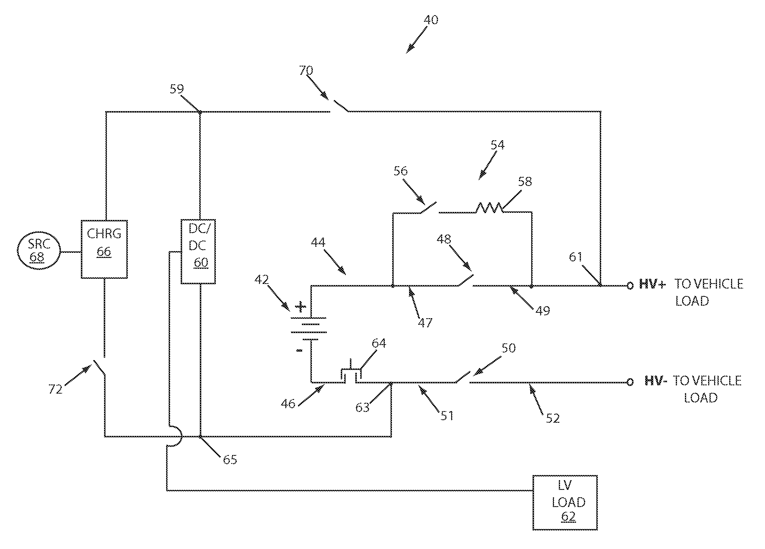
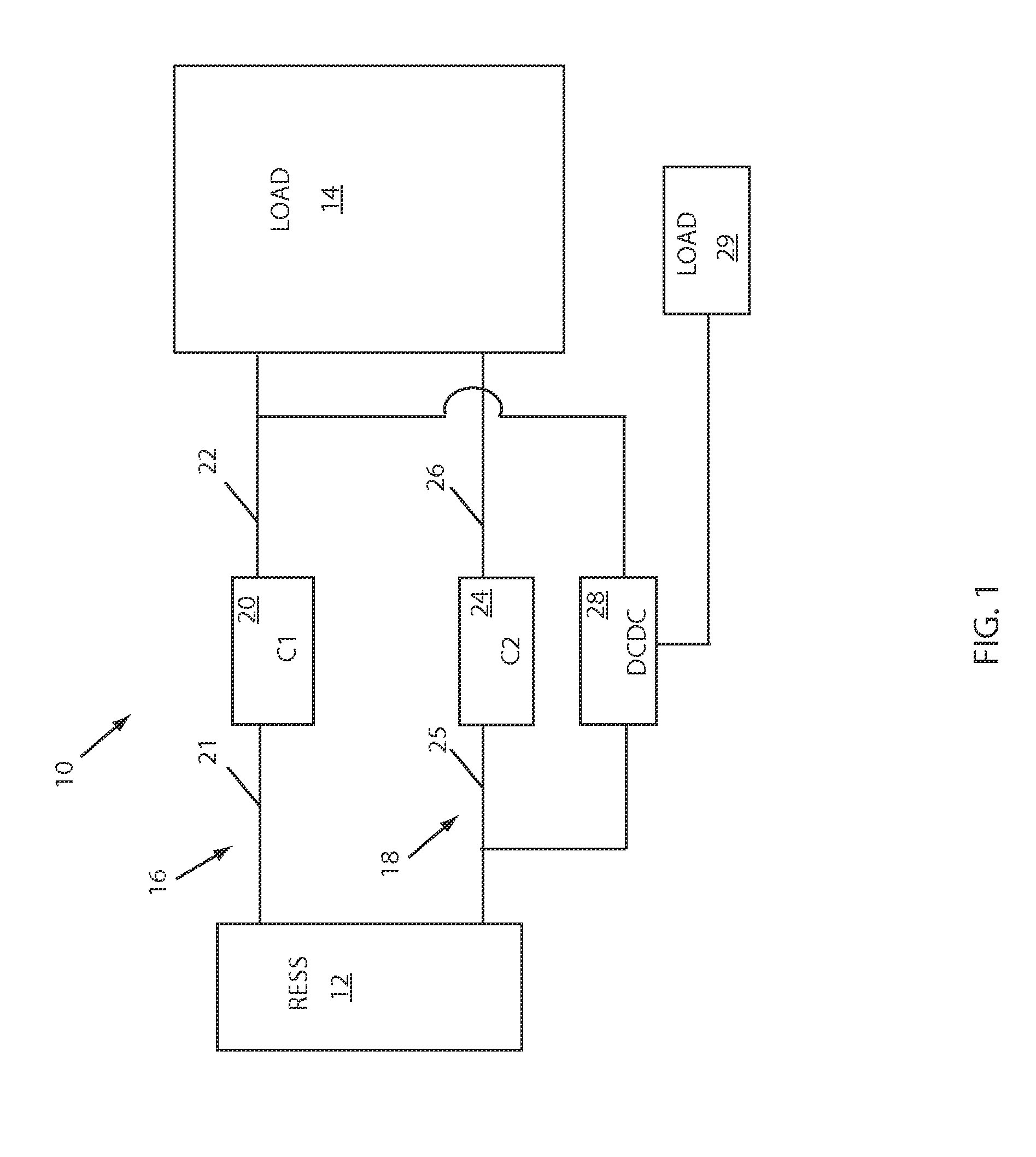
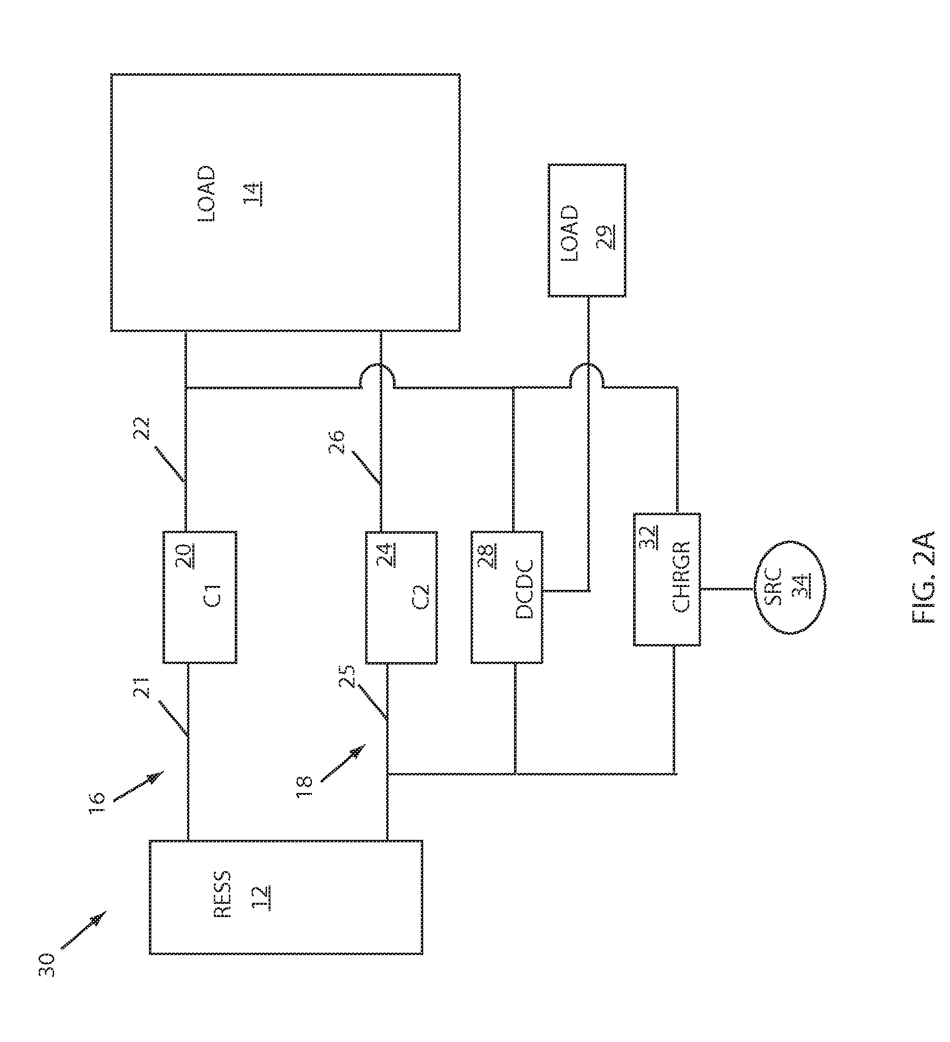
[0009]Systems and apparatus are presented that enable a DC / DC converter, coupled to a rechargeable energy storage system (RESS) and configured to support a low voltage load, to operate while the RESS is being charged, as well as operate while the RESS is not being charged but is supporting a high voltage (HV) load. At the same time, a system can limit or prevent unnecessary energizing of the DC / DC converter, charger and / or other apparatus to improve overall safety and efficiency. By way of example, an electrical circuit for a vehicle can include a RESS coupled to first and second voltage buses of opposing polarity, a charger configured to couple the RESS to an energy source during a RESS charging event, and a DC / DC converter coupled to the first and second voltage buses, wherein the DC / DC converter is configured for operation during the charging process and during vehicle propulsion.
[0010]An example system can include a RESS having a first polarity terminal coupled to a first voltage bus and a second opposing polarity terminal coupled to a second voltage bus; a first primary contactor configured to couple a first portion of the first voltage bus to a second portion of the first voltage bus; and a second primary contactor configured to couple a first portion of the second voltage bus to a second portion of the second voltage bus. In this manner each primary contactor can couple an energy side (first) portion of a voltage bus to a load side (second) portion of the voltage bus. A system can further include a DC / DC converter configured to step down the voltage of the RESS to support a low voltage load. In an example system, the DC / DC converter can be coupled to a first (energy) portion of one of the voltage buses, and to a second (load) portion of the remaining voltage bus. By way of example, a system for an electric or hybrid electric vehicle can include a DC / DC converter coupled to a RESS portion of one HV voltage bus, and a vehicle (load) portion of a second (opposing polarity) HV voltage bus. With both primary contactors closed, the vehicle sides of the HV voltage buses can be energized to support various HV vehicle loads, and the DC / DC converter can support low voltage loads. By controllably closing selected contactors of a system, a DC / DC converter can support a low voltage load without unnecessary energizing of an HV vehicle load. By way of example, but not limitation, the invention enables a DC / DC converter to support a low voltage system during vehicle preconditioning processes, low voltage battery maintenance, and HV battery charging periods.
[0011]In an example embodiment, a DC / DC converter can be controllably coupled to a load portion of one of the two voltage buses by an auxiliary contactor. By way of example, a charger can also be controllably coupled to the load portion of one voltage bus by the auxiliary contactor, and in addition, can be controllably coupled to an energy portion of the other voltage bus by a charger contactor. A pre-charge circuit can be disposed to controllably charge a load side of a voltage bus. In an example embodiment, the DC / DC converter can be arranged to benefit from the precharge circuit to avoid damage to its components caused by a high charge inrush.

Problems solved by technology

While regenerative braking during vehicle operation can re-energize a high voltage (HV) battery to a limited extent, additional battery recharging is also necessary.
However, the charging process itself can require various communications and operations by low voltage devices.
Because the main contactors are typically open during the charging process, a DC / DC converter coupled to a high voltage bus on the vehicle side of the main contactors cannot be energized by the RESS during the charging process, and therefore cannot support the low voltage battery and vehicle loads associated with the charging or preconditioning processes.
A solution that adds loads that reduce the efficiency of the charging process is generally undesirable.
Such a condition is generally undesirable because parasitic loads at the DC / DC converter can drain energy away from the high voltage battery.
In addition such a configuration can complicate servicing procedures.
However, this approach requires duplication of sophisticated circuitry and control, which is redundant and not cost-efficient.

Method used


Image

  • Low cost charger circuit with precharge
  • Low cost charger circuit with precharge
  • Low cost charger circuit with precharge

Examples


Embodiment Construction

[0019]As required, example embodiments of the present invention are disclosed. The various embodiments are meant to be non-limiting examples of various ways of implementing the invention and it will be understood that the invention may be embodied in alternative forms. The present invention will be described more fully hereinafter with reference to the accompanying drawings in which like numerals represent like elements throughout the several figures, and in which example embodiments are shown. The figures are not necessarily to scale and some features may be exaggerated or minimized to show details of particular elements, while related elements may have been eliminated to prevent obscuring novel aspects. The specific structural and functional details disclosed herein should not be interpreted as limiting, but merely as a basis for the claims and as a representative basis for teaching one skilled in the art to variously employ the present invention. For example, while the exemplary ...


PUM


Abstract

A low cost charger circuit with pre-charge functionality can include a DC / DC converter arranged in parallel with a charger device. When used for electrified vehicle applications, the DC / DC converter can be configured to operate during vehicle propulsion, restorable energy storage system (RESS) recharging, and while only the DC / DC converter needs to be energized. A DC / DC converter can be coupled to a first high voltage bus on a load side of a primary contactor, and to a second high voltage bus on an energy side of a primary contactor. A pre-charge circuit can controllably charge a voltage bus and protect a DC / DC converter against high inrush current. An auxiliary contactor can controllably couple a DC / DC converter to a load portion of a high voltage bus. It can also couple a charger thereto. A charger contactor can controllably couple a charger device to an energy portion of a high voltage bus.

Description

BACKGROUND OF INVENTION[0001]1. Field of Invention[0002]This invention relates generally to charging circuits for high voltage batteries, and more particularly to high voltage circuits for a vehicle with an electrified propulsion system.[0003]2. Background Art[0004]Electric and hybrid electric vehicles rely on a rechargeable energy storage system (RESS), such as a high voltage battery or battery pack, to provide power for an electric drive system. While regenerative braking during vehicle operation can re-energize a high voltage (HV) battery to a limited extent, additional battery recharging is also necessary. Accordingly, a typical high voltage battery pack can cooperate with a charger device configured to couple it to a power source such as an electric utility. For example, a charger can plug into an electrical outlet at a residence or charging station to enable battery pack recharging.[0005]A charging process is typically conducted while a vehicle is parked and turned off. In a t...

Claims


Application Information

Patent Timeline
Patent Type & Authority Patents(United States)
IPC IPC(8): H02J7/00B60L11/18B60L3/04B60L3/00
CPCB60L3/0046B60L3/0092B60L3/04B60L11/1816H02J7/0027B60L2210/12B60L2210/14B60L2270/20Y02T10/7005Y02T10/7225Y02T10/7233Y02T90/127Y02T90/14Y02T10/7072B60L53/14Y02T10/70Y02T10/72H02J7/0013H02J2310/48Y02T90/12
Inventor BILEZIKJIAN, JOHN PETERCALLICOAT, DEBBI
Owner FORD GLOBAL TECH LLC
Why Eureka
Try Eureka