
Steel wrapped pressure vessel

a pressure vessel and steel technology, applied in vessel construction details, transportation and packaging, manufacturing tools, etc., can solve the problems of lower mechanical properties along the transverse axis of longitudinal filament composites, reduced tensile strength of reinforcing fibers, and significant stiffness of cut ends of wires, so as to achieve good damage resistance protective coating

Active Publication Date: 2016-02-23
WIRETOUGH CYLINDERS
View PDF41 Cites 12 Cited by
  • Summary
  • Abstract
  • Description
  • Claims
  • Application Information

AI Technical Summary

Benefits of technology

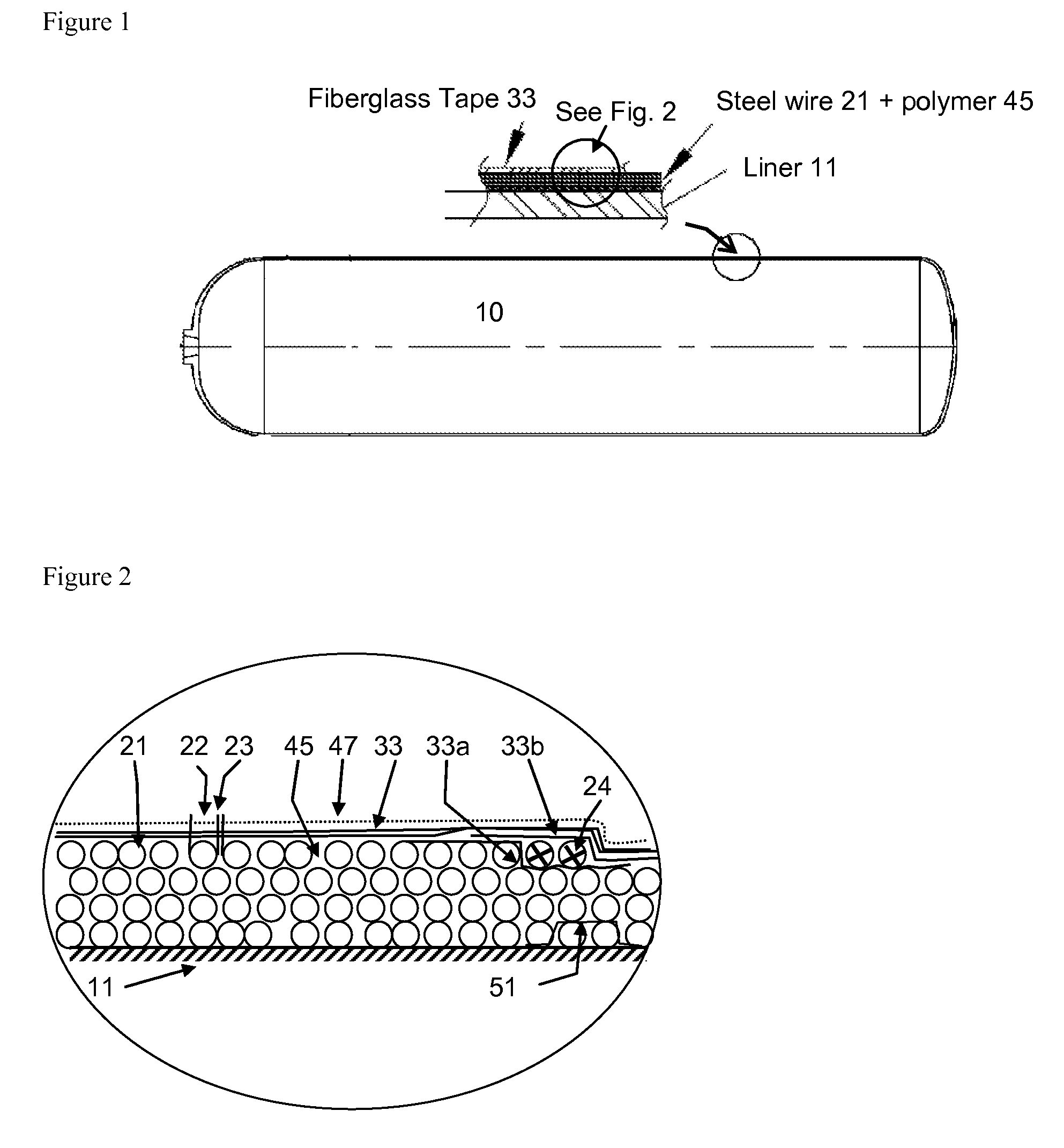
The patent describes how to protect and smoothly wind a wire using a non-metallic fabric tape. By placing a tape over the wire and rotating a cylinder, the wire is cut and placed between layers of tape, resulting in a smooth finish. The tape also wraps around the full cord reinforcement area and provides a protective coating to the cylinder, resistant to damage. This method can be used with any width of tape as long as it is compliant to the surface of the liner and the winding process.

Problems solved by technology

However, there has been a challenge in transferring the tensile strength of the reinforcing fibers to the vessel structure.
Composites made with longitudinal filaments, however, have lower mechanical properties along the transverse axis.
When the cylinder winding filaments are steel wire or cords, the cut ends of wires have significant stiffness and do not conform to the curvature of the liner.
This causes a problem which Steiner in U.S. Pat. No. 4,113,132 proposed welding the wire ends to the adjoining wires.
This works in heavy gauge wires, however, is impractical in thin high carbon wires.
Once wrapped, the cylinder is still exposed to external damage and degradation.

Method used


Image

  • Steel wrapped pressure vessel
  • Steel wrapped pressure vessel
  • Steel wrapped pressure vessel

Examples


Embodiment Construction

[0017]Recently a type of light weight pressure vessel was proposed by Prakash in US application 2009 / 0095796 where a high strength thin walled steel liner was circumferentially wrapped with 2000-6000 MPa tire cord quality steel wire. This application is incorporated herein by reference in its entirety. The steel wire or cord can be in the diameter range of 0.05 to 2.5 mm, preferably 0.10 to 2.0 mm. This vessel exhibited a great improvement in burst strength while maintaining a light weight structure comparable to carbon fiber wrapped pressure vessels, but at a much lower cost. Nevertheless, this Prakash cylinder had the same issues of adhering the cut ends of the steel wire to prevent damage to the structure. Prakash, like those inventors before him, had to insure the cut end did not get exposed during and after curing of the polymer.

[0018]This invention relates to a pressure vessel which is light in weight and is used for the storage of gas and is an improvement over the earlier Pr...


PUM

PropertyMeasurementUnit
thicknessaaaaaaaaaa
diameteraaaaaaaaaa
diameteraaaaaaaaaa

Abstract

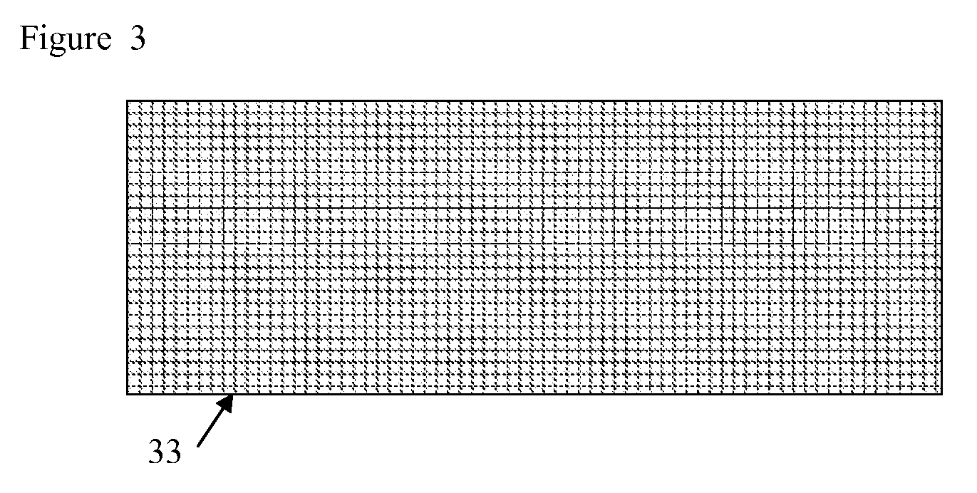
A light weight pressure vessel (10) has been proposed. The vessel (10) is made of a steel, aluminum or non-metal liner (11) which is reinforced with high strength steel wires (21) of 2000-7000 MPa strength. The matrix is filled with a polymer epoxy resin (45). A top layer of fabric tape (33) soaked in resin (45) has been used to embed the finish end (24) of the wire (21) and to provide a protective layer over the wire reinforced area. The mesh or net fabric wrap tape (33) has periodic openings to allow penetration of polymer epoxy resin (45). A top coat of a UV resistant polyurethane paint (47) has been applied.

Description

RELATED APPLICATIONS[0001]This application is a continuation in part of U.S. application Ser. No. 12 / 235,856 entitled “Wire Wrapped Pressure Vessels” filed on Sep. 23, 2008.FIELD OF INVENTION[0002]Steel wire or cord wrapped pressure vessels with a damage protective layer.BACKGROUND OF THE INVENTION[0003]A pressure vessel is a container to withstand a pressure differential between inside and outside. A pressure vessel may comprise of multiple layers of materials to provide various required properties. The inside and outside of the vessel may have special properties to meet the environment while the inner layers may be designed to provide strength, fatigue and fracture toughness to the vessel. The design is governed by standard pressure vessel equations published in books such as Harvey (see reference), and standards such as ASME Section VIII, Div. I, DOT FMVSS 304, ANSI-NGV-2, ISO11439 and several others. As an example, Dallum in U.S. Pat. No. 5,024,342 has shown a multilayer contain...

Claims


Application Information

Patent Timeline
Patent Type & Authority Patents(United States)
IPC IPC(8): F17C1/06F17C1/02B65D13/00B21C19/00
CPCB65D13/00B21C19/00F17C1/06F17C2201/0109F17C2201/035F17C2201/054F17C2201/056F17C2201/058F17C2203/012F17C2203/0604F17C2203/066F17C2203/0619F17C2203/0636F17C2203/0639F17C2203/0646F17C2203/0656F17C2203/0658F17C2203/0663F17C2209/2154F17C2221/011F17C2221/012F17C2221/033F17C2221/035F17C2223/0123F17C2223/0153F17C2223/036F17C2260/011F17C2260/012F17C2260/042F17C2260/053F17C2270/0168F17C2270/0186Y02E60/321Y02E60/32
Inventor PRAKASH, AMITSHARP, GEORGE RICHARDDEEKEN, BRIAN TOWNSENDHEAD, WILLIAM JAMESTHOMSON, WILLIAM H
Owner WIRETOUGH CYLINDERS
Learn More