Dual-view laser-based three-dimensional capture system and method for employing the same

a three-dimensional capture and laser technology, applied in the field of vision system cameras, can solve problems such as three-dimensional (3d), and achieve the effect of less (or, more compact overall unit, and reduced signal-to-nois

Active Publication Date: 2016-03-01
COGNEX CORP
View PDF23 Cites 18 Cited by
  • Summary
  • Abstract
  • Description
  • Claims
  • Application Information

AI Technical Summary

Benefits of technology

[0004]This invention overcomes disadvantages of the prior art by providing a 3D laser capture system, and method for employing the same, that avoids a shadow effect and allows for straightforward set-up and use of the system in imaging the surface profile of an object. The system includes a camera and a cylindrical laser. The camera is provided with a head assembly that includes a lens configuration and a pair of mirrors that generate two simultaneous views, respectively of two opposite sides of the object. The two views are projected by the mirrors and lens configuration onto discrete portions of the camera's image sensor (or “imager”). The separate images captured on each of the two portions of the sensor are both analyzed by the systems vision system processor, thereby allowing the processor's profiling algorithm to analyze the surface from two different viewing angles concurrently. In this manner, portions of the laser that are blocked in one view are generally visible in the other view, and combining the overall image data set yields a result that exhibits significantly less (or in many instances no) shadow effect. This arrangement allows for a more compact overall unit, with a single camera (that can use conventional optics) employed to acquire two separate images using a single laser, and reduced signal-to-noise since two images can be compared and any obvious noise filtered-out of the result. In embodiments, the optics can include a beam-splitting mirror to generate two images at the sensor. Alternatively, a second lens can be employed to provide a second field of view.

Problems solved by technology

Undesirably, conventional three-dimensional (3D) laser capture / profile systems generally suffer from a shadow effect, in which portions of the laser beam blocked by the target object result in blank zones in the resulting imaged 3D model of the object.

Method used


Image

  • Dual-view laser-based three-dimensional capture system and method for employing the same
  • Dual-view laser-based three-dimensional capture system and method for employing the same
  • Dual-view laser-based three-dimensional capture system and method for employing the same

Examples


Embodiment Construction

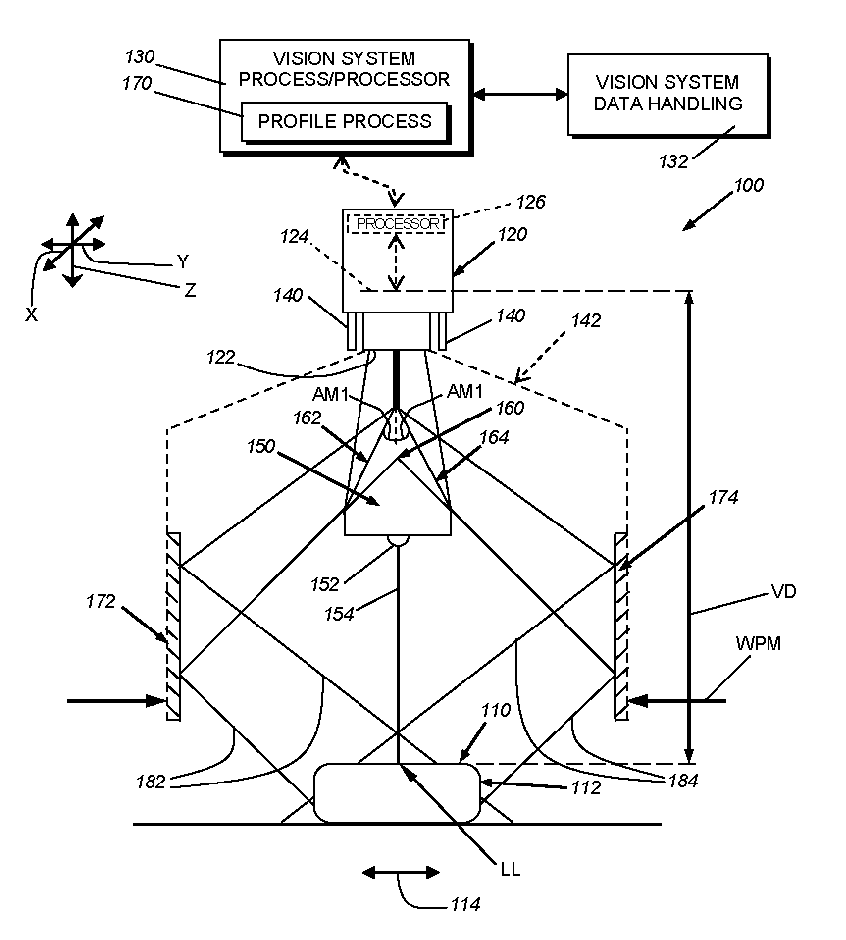
[0013]FIG. 1 is a system 100 for 3D capture (profiling) of the surface 110 of an exemplary object 112. The object can be stationary or in relative motion (arrow 114) with respect to the system 100 along a predetermined direction. It is contemplated in instances of relatively motion that either of (or both) the system and the object moves. Where motion occurs, the system can perform a scan of the surface 110, by acquiring images (image frames) at each of a large number of locations along the surface. This is described further below.

[0014]The system 100 includes a vision system camera 120 that can be any appropriate camera assembly having a fixed or removable lens arrangement 122 that focuses received light onto an image sensor (or simply termed “sensor”) 124 that defines the camera's image plane. The sensor is operatively connected to the camera's on-board processor assembly 126. The processor assembly 126 can control system operation and / or various regulation processes, including bu...


PUM


Abstract

This invention provides a 3D laser capture system, and method for employing the same, that avoids a shadow effect and allows for straightforward set-up and use of the system in imaging the surface profile of an object. A camera is provided with a head assembly that includes a lens configuration and a pair of mirrors that generate two simultaneous views, of opposite object sides. The two views are projected by the mirrors and lens configuration onto discrete portions of the camera's image sensor. The separate images captured on each of the two portions of the sensor are both analyzed by the systems vision system processor, thereby allowing the processor's profiling algorithm to analyze the surface from two different viewing angles concurrently. Portions of the laser blocked in one view are generally visible in the other view. Alternatively, a second lens can be employed to provide a second field of view.

Description

FIELD OF THE INVENTION[0001]This invention relates to vision system cameras and more particularly to vision system cameras adapted to image surface profiles.BACKGROUND OF THE INVENTION[0002]A laser beam profiler (also termed simply a “laser profiler”) captures and determines the spatial intensity (three dimensional) profile of a fan or “curtain” of a laser beam at a particular plane transverse to the beam propagation path. In a conventional arrangement, a single camera captures the profile of the beam on the object surface. The camera typically resides above the surface plane and the camera lens axis resides at an acute angle (i.e. off-axis) relative to the plane so as to capture the deviation of the laser line upon the surface. This deviation represents the profile of the surface. Laser profilers are useful in a wide range of inspection and manufacturing operations where the user desires to measure and characterize surface details of a planar object via triangulation. One example i...

Claims


Application Information

Patent Timeline
Patent Type & Authority Patents(United States)
IPC IPC(8): H04N13/02
CPCH04N13/0271G01B11/2545H04N13/207H04N13/388H04N13/271
Inventor LLOYD, ROBERTNUNNINK, LAURENS
Owner COGNEX CORP
Why Eureka
Try Eureka