Injection device for introducing a urea solution into the exhaust tract of an internal combustion engine

a technology of injection device and internal combustion engine, which is applied in the direction of machines/engines, mechanical equipment, applications, etc., can solve the problems of complex, expensive, and easy failure, and achieve the effect of easy actuation of pressure elements, and increased closing process speed

a technology of injection device and internal combustion engine, which is applied in the direction of machines/engines, mechanical equipment, applications, etc., can solve the problems of complex, expensive, and easy failure, and achieve the effect of easy actuation of pressure elements, and increased closing process speed

US9279400B2Inactive Publication Date: 2016-03-08ROBERT BOSCH GMBH

Image

  • Injection device for introducing a urea solution into the exhaust tract of an internal combustion engine
  • Injection device for introducing a urea solution into the exhaust tract of an internal combustion engine
  • Injection device for introducing a urea solution into the exhaust tract of an internal combustion engine

Examples


Embodiment Construction

[0022]In the following description of the figures, expressions such as “top” and “bottom” serve for improved explanation of the schematic illustrations of an exemplary embodiment of the invention shown in the respective figure, without restricting the invention to the exemplary embodiment shown or to a certain orientation or installation position.

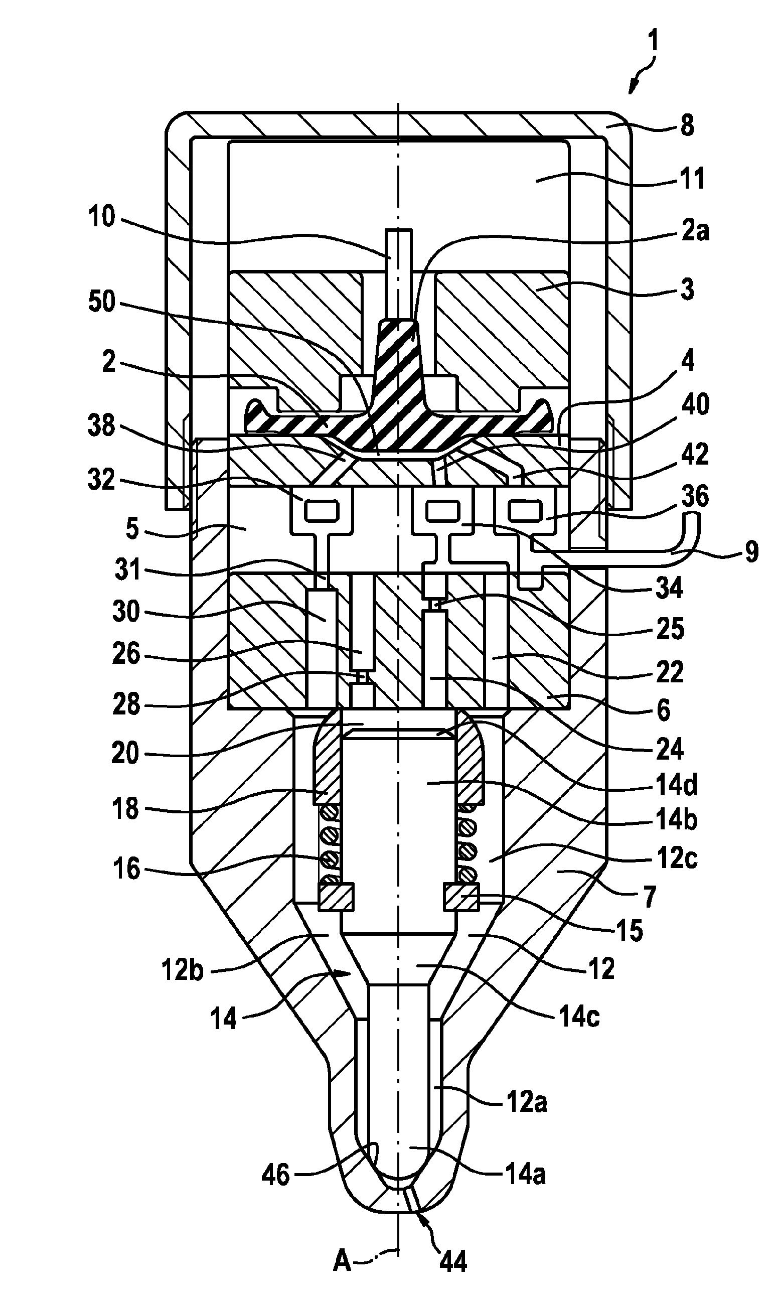
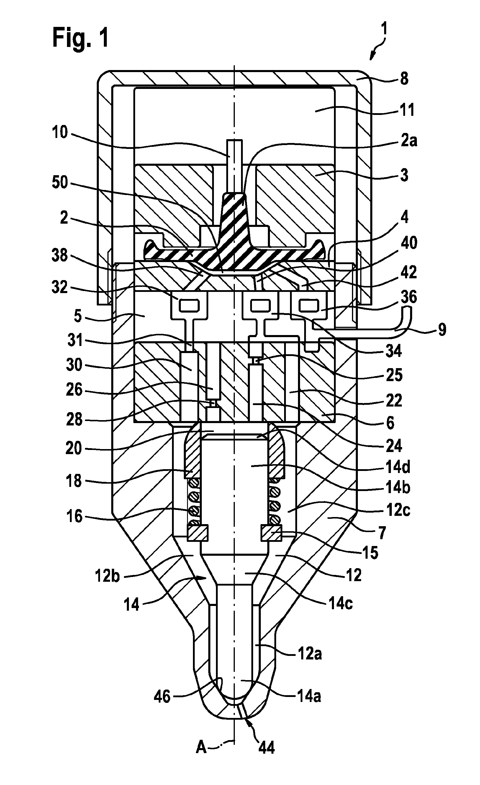
[0023]FIG. 1 shows a sectional view of a first exemplary embodiment of an injection device 1 according to the invention.

[0024]An injection device 1 according to the invention has a nozzle body 7 which is for example of cylindrical form about a longitudinal axis A and along the longitudinal axis A of which is formed an injection chamber 12. The injection chamber 12 has a first cylindrical region 12a illustrated at the bottom in FIG. 1 and has a second cylindrical region 12c arranged thereabove.

[0025]In a plane which is oriented at right angles to the longitudinal axis A, the first cylindrical region 12a has a smaller cross section than the s...


PUM


Abstract

The invention relates to an injection device (1), designed in particular for injecting fluid into an exhaust tract of an internal combustion engine, having a valve needle (14), an injection chamber (12) having at least one injection opening (44), and a control chamber (20). The injection device (1) is designed such that a pressure differential between the injection chamber (12) and the control chamber (20) brings about a displacement of the valve needle (14) between an open position in which a fluid flow through the injection opening (44) from the injection chamber (12) is released, and a closed position, in which the injection opening (44) is closed off. The injection chamber (22) and the control chamber (20) are hydraulically connected to an inlet (40, 42; 9), such that a pressure rise in the inlet (40, 42; 9) results in a pressure rise in the injection chamber (12), and a pressure rise in the control chamber (20) delayed in time relative to the pressure rise in the injection chamber (12), and said pressure differential brings about a displacement of the valve needle (14) from the closed position into an open position.

Description

BACKGROUND OF THE INVENTION[0001]The demands placed on the exhaust-gas quality of internal combustion engines, in particular of internal combustion engines for driving motor vehicles, have steadily increased in recent years. In the case of diesel engines in particular, NOx emissions constitute a problem, which is counteracted by means of so-called SCR catalytic converters. In an SCR catalytic converter, environmentally harmful NOx is converted with the aid of NH3, which is supplied to the catalytic converter generally in the form of an aqueous urea solution, into N2 and H2O.[0002]To supply the urea solution to the exhaust gases of the internal combustion engine, a dosing system is required, which conventionally comprises an electrically operated pump and an electrically actuated dosing valve. Such dosing systems are cumbersome and expensive to produce, assemble and maintain.[0003]EP 1 878 920 A1 discloses a liquid pump having an inlet, an outlet, a pump chamber for receiving the liq...

Claims


Application Information

Patent Timeline
08 Mar 2016
Publication
US9279400B2
IPC
F02M47/02; F02M7/02; F01N3/20; F02M57/02; F01N3/36
CPC
F02M47/025; F01N3/20; F01N3/206; F01N3/2066; F01N3/36; F02M7/02; F02M57/027; F01N2610/1453
Inventors
DOEHRING, JOCHEN; RIPPER, WOLFGANG