Parallel dynamic compressor arrangement and methods related thereto

a compressor arrangement and dynamic technology, applied in the direction of machines/engines, positive displacement liquid engines, lighting and heating apparatus, etc., can solve the problems of efficiency gain and require less space, and achieve the effect of less space, higher discharge pressure and efficiency gain

Active Publication Date: 2016-03-15
EXXONMOBIL UPSTREAM RES CO
View PDF82 Cites 7 Cited by
  • Summary
  • Abstract
  • Description
  • Claims
  • Application Information

AI Technical Summary

Benefits of technology

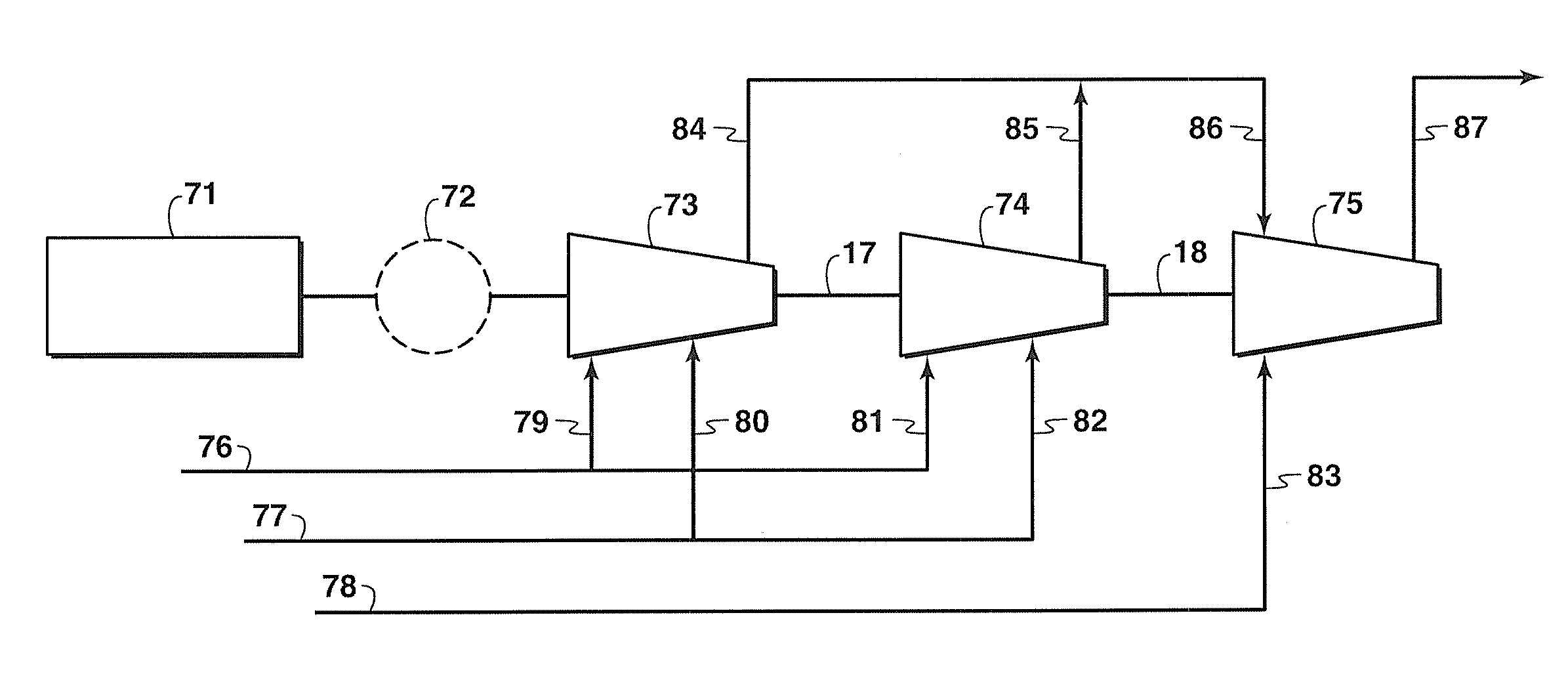
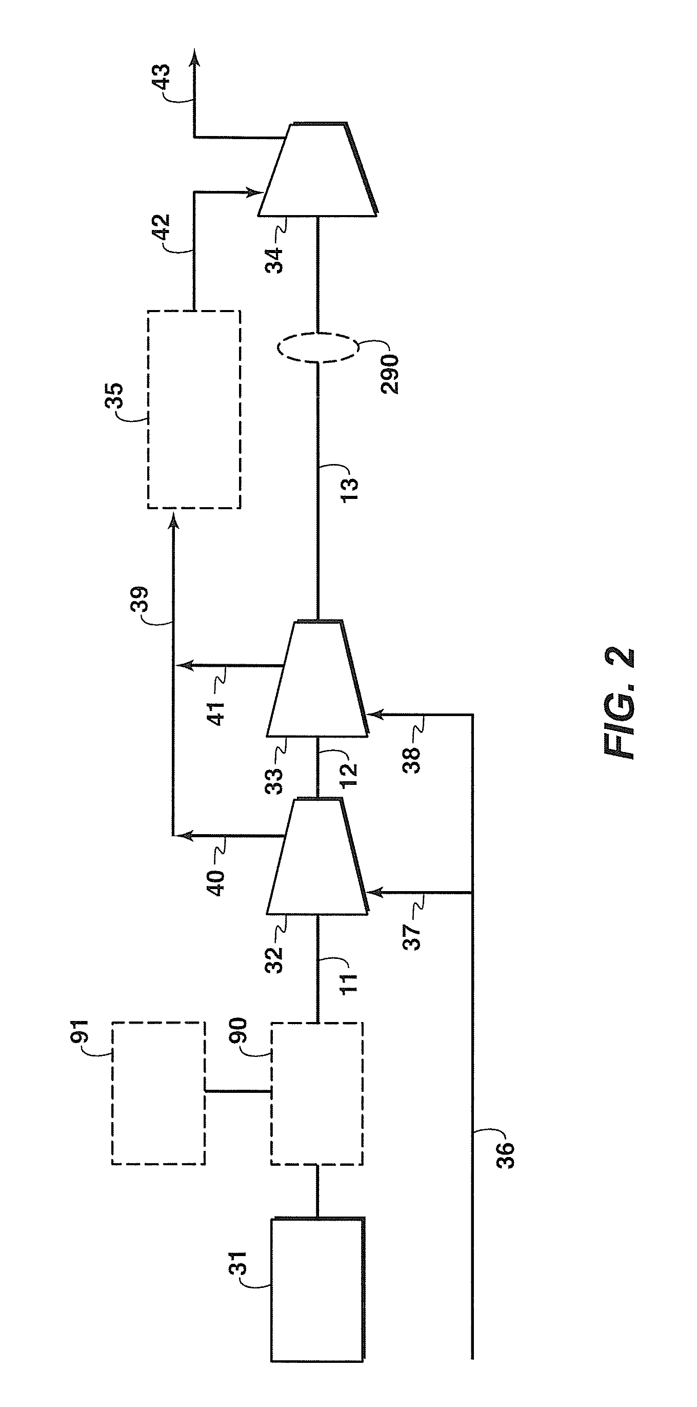
[0010]Provided are apparatus and methods of compressing gas, e.g., natural gas, which include one prime mover and three or more compressor bodies wherein the main drive shafts of all the compressor bodies are connected in series to the prime mover. Use of the apparatus increases efficiency and output capacity by compressing a fluid in two or more stages.
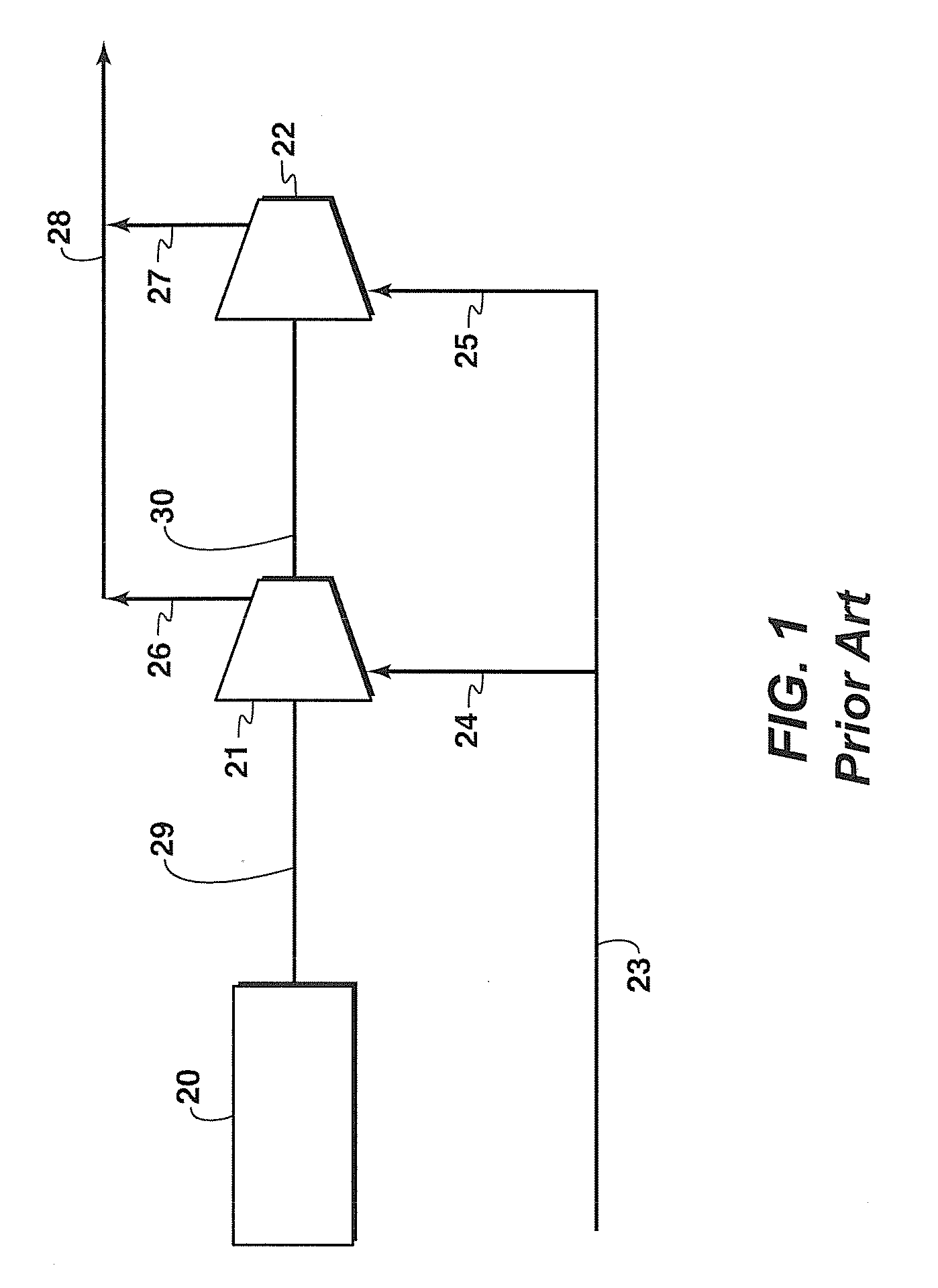
[0012]Using a higher powered prime mover rather than two smaller power units results in efficiency gain and requires less space. Compressor body pressure rating is also related to the inverse of the impeller diameter. Thus, the apparatus provides higher discharge pressures than a conventional design, since it will utilize multiple smaller diameter, therefore higher pressure, compressors instead of a single larger, potentially lower pressure compressor.
[0013]For the same capacity, the provided apparatus and methods enable the use of smaller compressors, which are easier to maintain and operate, and may be more reliable.

Problems solved by technology

Using a higher powered prime mover rather than two smaller power units results in efficiency gain and requires less space.

Method used


Image

  • Parallel dynamic compressor arrangement and methods related thereto
  • Parallel dynamic compressor arrangement and methods related thereto
  • Parallel dynamic compressor arrangement and methods related thereto

Examples


Embodiment Construction

[0024]In the following detailed description section, the specific embodiments of the present invention are described in connection with preferred embodiments. However, to the extent that the following description is specific to a particular embodiment or a particular use of the present invention, this is intended to be for exemplary purposes only and simply provides a description of the exemplary embodiments. Accordingly, the invention is not limited to the specific embodiments described below, but rather, it includes all alternatives, modifications, and equivalents falling with the scope of the appended claims.

[0025]The term “compressor” as used herein refers to a device used to increase the pressure of an incoming fluid by decreasing its volume. The compressors referenced herein specifically include the dynamic type (centrifugal, axial and mixed-flow) and exclude reciprocating compressors.

[0026]The term “compressor body” as used herein refers to a casing which holds the pressure s...


PUM


Abstract

This disclosure is directed to a novel arrangement for equipment used to compress fluids. A single prime mover is connected to a plurality of compressors. A supply conduit with parallel branch conduits directs fluid to be compressed to at least two compressors and parallel output conduits from each compressor are connected to a common output conduit, which directs compressed fluids to at least one additional compressor.

Description

CROSS REFERENCE TO RELATED APPLICATIONS[0001]This application is the National Stage of International Application No. PCT / US2011 / 034768, filed May 2, 2011, which claims priority from both U.S. patent application No. 61 / 347,221 filed on May 21, 2010, entitled PARALLEL DYNAMIC COMPRESSOR ARRANGEMENT and U.S. patent application No. 61 / 474,585 filed on Apr. 12, 2011 entitled PARALLEL DYNAMIC COMPRESSOR ARRANGEMENT AND METHODS RELATED THERETO, the entirety of which is incorporated by reference herein.FIELD OF THE DISCLOSURE[0002]Embodiments of the disclosure relate to apparatus and methods of compressing gas, such as natural gas. More particularly, embodiments of the disclosure relate to methods and apparatus for compressing gas using parallel compressor bodies coupled to a prime mover.BACKGROUND OF THE DISCLOSURE[0003]This section is intended to introduce various aspects of the art, which may be associated with exemplary embodiments of the present invention. This discussion is believed t...

Claims


Application Information

Patent Timeline
Patent Type & Authority Patents(United States)
IPC IPC(8): F04B25/00F04D25/06F04D25/04F04D25/16F04B41/06
CPCF04D25/16F04D25/04F04D25/06F04B25/00F04B41/06F25J1/0022F25J1/0283F25J1/0287F25J1/0294F25J2230/20
Inventor SITES, OMAR, ANGUS
Owner EXXONMOBIL UPSTREAM RES CO
Why Eureka
Try Eureka