
Device and method for managing an electronic control unit of a vehicle

a technology of electronic control unit and vehicle, which is applied in the direction of position/direction control, structural/machine measurement, registering/indicating, etc., can solve the problems of large volume of tools, increased complexity of on-board diagnostic system, and increased complexity of vehicles

Active Publication Date: 2016-03-15
INNOVATION GAP
View PDF24 Cites 1 Cited by
  • Summary
  • Abstract
  • Description
  • Claims
  • Application Information

AI Technical Summary

Benefits of technology

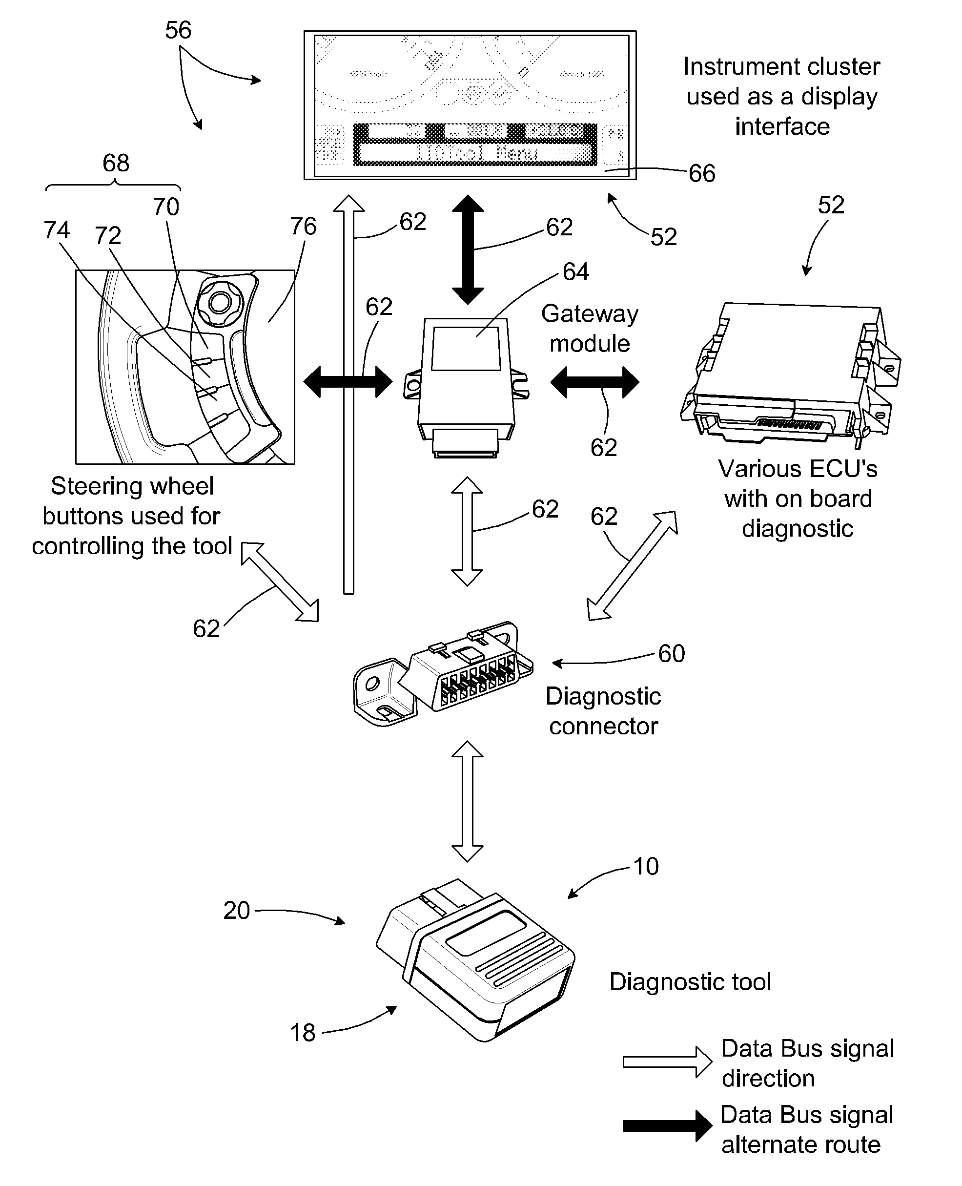
This patent is about a device that can be added to a vehicle to provide a user interface for controlling it. The device is designed to be self-contained and easily portable, so it doesn't require any additional cables, computers, or power supplies. The device uses existing components of the vehicle, like buttons and a display screen, to control it. This makes the device cost-effective and easy to use.

Problems solved by technology

In more recent days, vehicles have more electronic modules and components and on-board diagnostic systems are therefore more complex.
Such devices range from relatively simple handheld devices available to consumers for a cost which is generally lower than more complex and expensive tools made especially for dealerships.
However, such tools are generally bulky and relatively expensive to manufacture, as well as to support and maintain, given that they have elaborate electronic components and circuitry, namely a display screen, buttons, or the like, as well as the related circuitry.
Moreover, the user is required to enter commands and information as well as view and receive information through an external device, which is typically handheld, and which may be awkward to handle and manipulate, given the normal driver's position in a vehicle.
However, by definition, such devices are generally limited in terms of use.

Method used


Image

  • Device and method for managing an electronic control unit of a vehicle
  • Device and method for managing an electronic control unit of a vehicle
  • Device and method for managing an electronic control unit of a vehicle

Examples


Embodiment Construction

[0030]In the following description, the same numerical references refer to similar elements. The embodiments, geometrical configurations, materials mentioned and / or dimensions shown in the figures or described in the present description are preferred embodiments only, given for exemplification purposes only.

[0031]In the context of the present invention, the expressions “device”, “add-on device”, “tool”, “electronic device” and any other equivalent expression and / or compound words thereof known in the art will be used interchangeably. Furthermore, the same applies for any other mutually equivalent expressions, such as “ECU”, “electronic component”, “vehicle component”, “electronic module”, “module” and any other equivalent expression and / or compound words thereof, as well as for “communication network” and “communication system”, for example, as also apparent to a person skilled in the art. Furthermore, and also in the context of the present description, the expressions “data buses”,...


PUM


Abstract

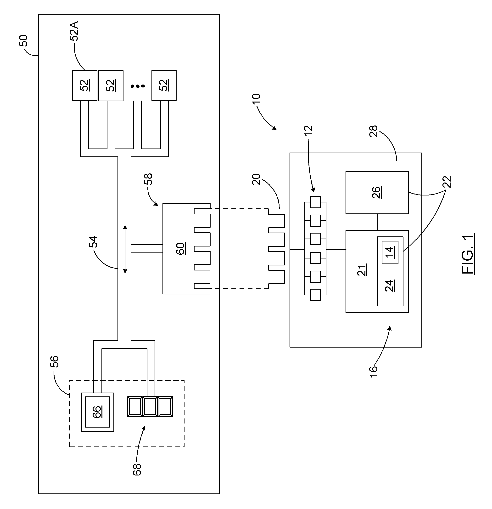
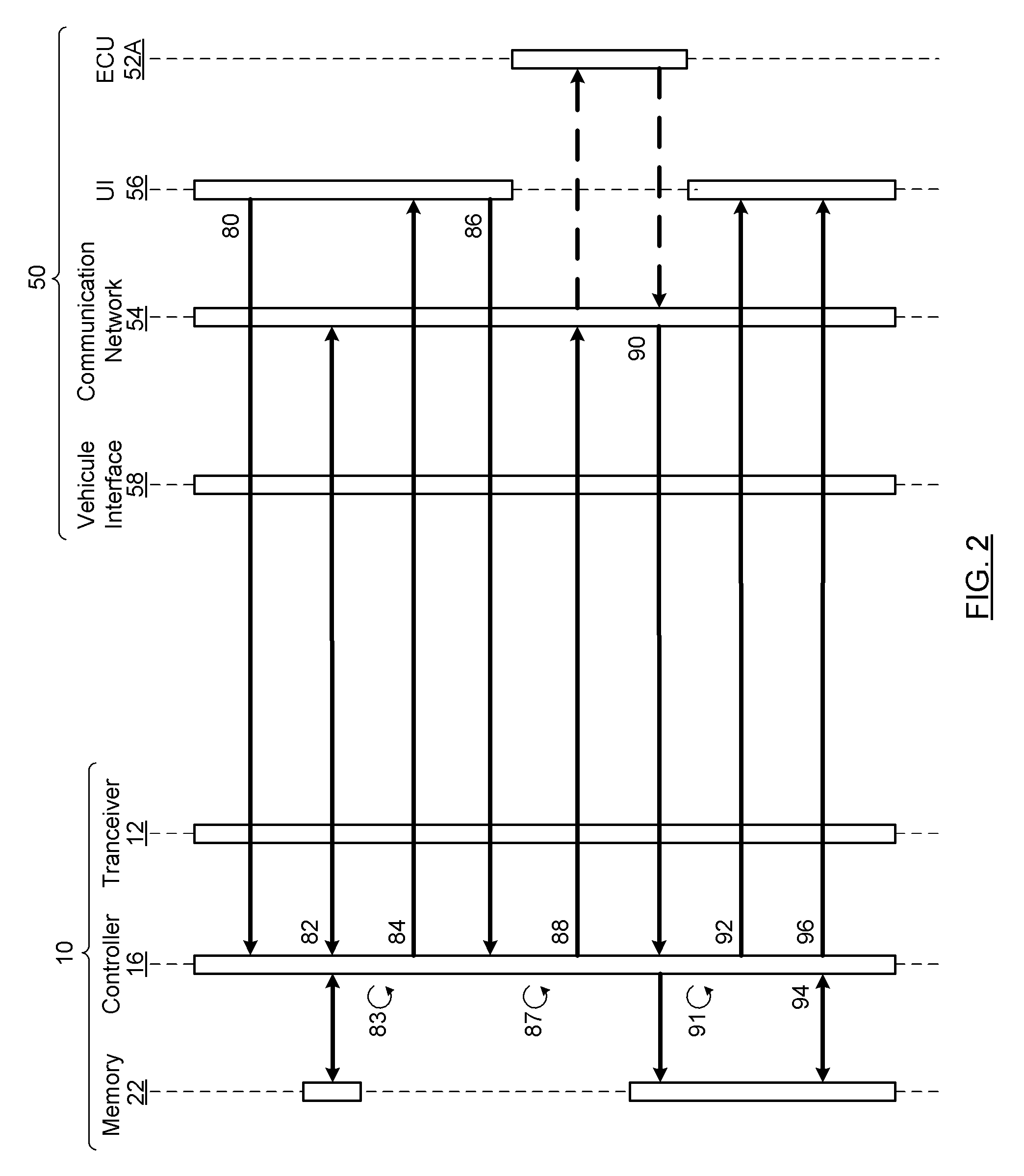
An add-on device and method for managing an electronic control unit (ECU) of a vehicle is disclosed. The add-on device includes a transceiver adapted for communicating with the communication network of a vehicle. The add-on device further includes a controller being communicatively connected to the transceiver, and adapted to generate a user-interface control signal addressed to the user interface of the vehicle, in order to manipulate the user interface of the vehicle and to present thereon command options prompting a user to enter a command selection in response to the command options presented. The controller is further adapted to receive the command selection from the user interface, and to generate in response thereto, an ECU control signal to be sent to the communication network for executing an operation with respect to a targeted ECU, in order to manage the targeted ECU from the user interface of the vehicle.

Description

RELATED APPLICATIONS[0001]This application is the U.S. National Phase under 35 U.S.C. §371 of International Application No. PCT / CA2011 / 001209, filed on Oct. 28, 2011, which in turn claims the benefit of U.S. Provisional Application No. 61 / 407,655, filed on Oct. 28, 2010, the disclosures of which Applications are incorporated by reference herein.FIELD OF THE INVENTION[0002]The present invention relates to the field of interfacing with vehicle components. More particularly, the present invention relates to add-on device for a vehicle for managing an electronic control unit (ECU) of the vehicle, as well as to a method, to a kit and to a processor-readable product for providing the same.BACKGROUND OF THE INVENTION[0003]Known in the art are diagnostic tools, generally used for reading indicators as to the state of health for various electronic modules of a vehicle. Most of today's vehicles have on-board self-diagnostic and reporting capabilities to help maintain or repair various systems...

Claims


Application Information

Patent Timeline
Patent Type & Authority Patents(United States)
IPC IPC(8): G06F19/00B60W50/08G07C5/08G01M17/00G06F17/00B60W50/04B60R16/023
CPCG06F17/00B60W50/045B60W50/08B60R16/0232G07C5/085G07C5/0808
Inventor SIMARD, CHRISTIANMEILLEUR, PATRICK
Owner INNOVATION GAP
Learn More