Electrostatic chucking device

a technology of chucking device and electric motor, which is applied in the direction of semiconductor/solid-state device manufacturing, basic electric elements, electric apparatus, etc., can solve the problems of poor product production, cracking of ceramic substrate, and fracture, etc., and achieves rapid movement and heat generation. , the effect of rapid heat generation

Active Publication Date: 2016-03-15
SUMITOMO OSAKA CEMENT CO LTD
View PDF6 Cites 9 Cited by
  • Summary
  • Abstract
  • Description
  • Claims
  • Application Information

AI Technical Summary

Benefits of technology

[0018]According to the electrostatic chucking device of the invention, since the plate-like body that mounts a plate-like specimen is made of a corrosion-resistant ceramic, the circular insulation member is provided in the circumferential edge portion between the electrostatic chucking portion and the base stage, and the heat radiation plate is provided on the principal surface of the base stage on the electrostatic chucking portion side, it is possible to make heat uniformly transferred in the plate-like body. In addition, it is possible to induce heat generated from the plate-like body to rapidly move toward the base stage using the circular insulation member and to rapidly radiate heat outside using the heat radiation plate provided on one principal surface of the base stage. Therefore, it is possible to uniformly transfer heat in the plate-like body that mounts a plate-like specimen and thus to prevent the occurrence of cracking or fracture caused by uneven heat transfer.

Problems solved by technology

However, in an electrostatic chucking device of the related art in which a ceramic substrate was used, since heat was unevenly transferred in the ceramic substrate, there was a problem in that the surface temperature of a plate-like specimen such as a silicon wafer which is mounted on the ceramic substrate became uneven in the in-plane direction, and thus variation in characteristic caused by the uneven surface temperature in the in-plane direction was caused in the obtained LSI, and, sometimes, poor products were produced.
In addition, since heat was unevenly transferred in the ceramic substrate, in a case in which a thermal stress was applied to the ceramic substrate, there was a problem in that the thermal stress was concentrated in regions in the ceramic substrate in which heat was easily transferred, and the ceramic substrate cracked, and, sometimes, fractured.

Method used


Image

  • Electrostatic chucking device
  • Electrostatic chucking device
  • Electrostatic chucking device

Examples


example 1

Production of an Electrostatic Chucking Device

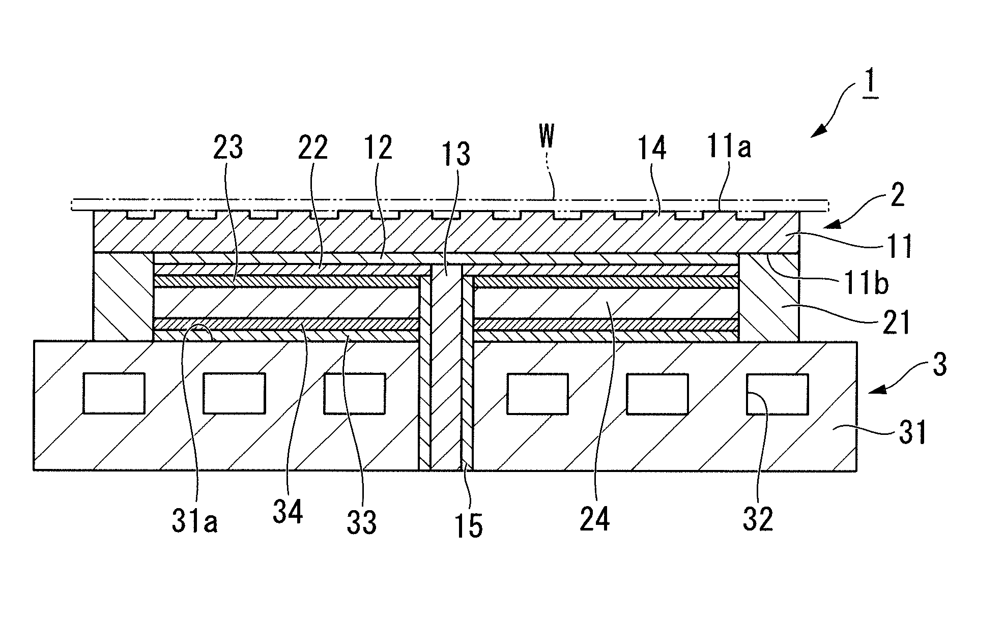
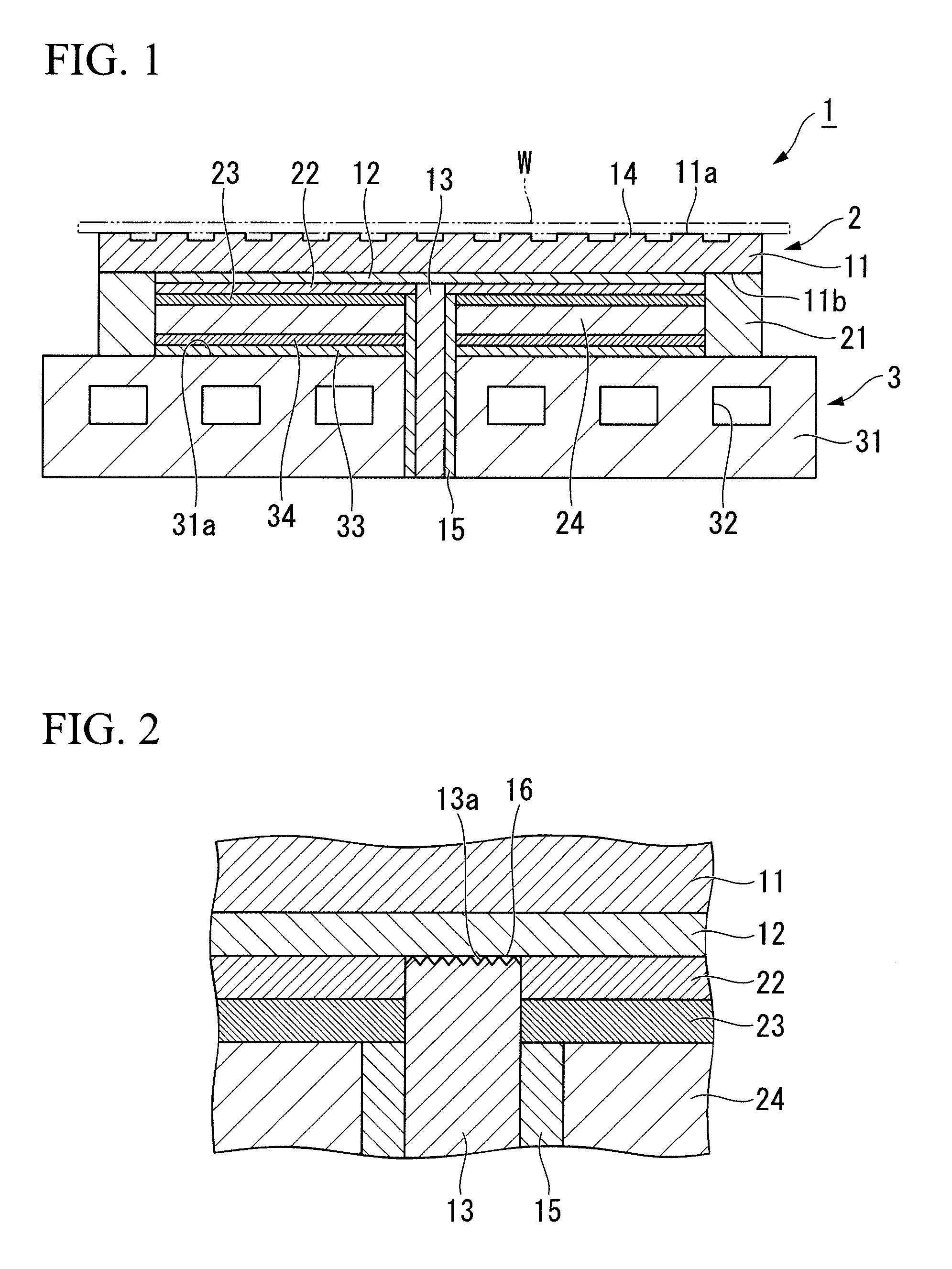
[0128]First, a plate-like body 11 made of yttrium aluminum garnet (YAG: Y3Al5O12) was prepared. The plate-like body 11 had a disc shape with a diameter of 300 mm and a thickness of 1 mm. In addition, the number of protrusion portions 14 with a height of 15 μm are formed on a top surface of the plate-like body 11, to which a wafer W was to be electrostatically adsorbed, so as to make the surface uneven, top surfaces of the protrusion portions 14 were used as surfaces on which the plate-like specimen W is mounted, and cooling gas was able to flow through grooves being formed between recess portions on the uneven surface and the electrostatically adsorbed plate-like specimen W.

[0129]In addition, a bottom surface 11a of the plate-like body 11 was defatted and washed using acetone, and conductive paste FC415 (manufactured by Fujikura Kasei Co., Ltd.) was applied to the bottom surface 11a using a screen printing method and the plate-like body ...

example 2

[0149]An electrostatic chucking device of Example 2 was produced according to Example 1 except that the plate-like body 11 was changed from yttrium aluminum garnet (YAG) to samarium oxide-added yttrium aluminum garnet (YAG.Sm) obtained by adding 10% by mass of samarium oxide (Sm2O3) to yttrium aluminum garnet (YAG), and the electrostatic chucking device was evaluated.

[0150]As a result, the variation in the in-plane temperature distribution of the silicon wafer was within ±0.5° C., and the occurrence of cracking or fracture was not observed on the top surface of the plate-like body.

example 3

[0151]An electrostatic chucking device of Example 3 was produced according to Example 1 except that the plate-like body 11 was changed from yttrium aluminum garnet (YAG) to gadolinium oxide-added yttrium aluminum garnet (YAG.Gd) obtained by adding 10% by mass of gadolinium oxide (Gd2O3) to yttrium aluminum garnet (YAG), and the electrostatic chucking device was evaluated.

[0152]As a result, the variation in the in-plane temperature distribution of the silicon wafer was within ±0.5° C., and the occurrence of cracking or fracture was not observed on the top surface of the plate-like body.


PUM


Abstract

The electrostatic chucking device 1 of the invention includes an electrostatic chucking portion 2 which includes a plate-like body 11, a top surface 11a of which is used as a mounting surface that mounts a plate-like specimen W, an electrostatic adsorption electrode 12 provided in the plate-like body 11 and a power-feeding terminal 13 that applies a direct-current voltage to the electrostatic adsorption electrode 12; and a base portion 31 that supports the electrostatic chucking portion 2, in which the plate-like body 11 is a corrosion-resistant ceramic, a circular insulation member 21 is provided in a circumferential edge portion between the electrostatic chucking portion 2 and the base portion 31, and a heat radiation plate 34 is provided on the top surface 31a of the base portion 31.

Description

TECHNICAL FIELD[0001]The present invention relates to an electrostatic chucking device, and, in more detail, to an electrostatic chucking device preferably used when carrying out a treatment such as plasma etching on a semiconductor substrate such as a silicon wafer.BACKGROUND ART[0002]In recent years, in the semiconductor industry which supports rapidly advancing IT technologies, there has been a demand for high integration or performance improvement of devices, and, accordingly, there has been a demand for additional improvement of micro-fabrication techniques in semiconductor-manufacturing processes as well. Even in semiconductor-manufacturing processes, etching techniques are one kind of important micro-fabrication technique, and, in recent years, among etching techniques, plasma etching techniques that can micro-fabricate a large area at a high efficiency have become mainstream.[0003]For example, an LSI-manufacturing process in which a silicon wafer is used is a technique in wh...

Claims


Application Information

Patent Timeline
Patent Type & Authority Patents(United States)
IPC IPC(8): H01L21/683H01L21/67
CPCH01L21/6833H01L21/67103
Inventor MORIYA, YOSHIAKIMIURA, YUKIOMAETA, SHINICHI
Owner SUMITOMO OSAKA CEMENT CO LTD
Why Eureka
Try Eureka