Coal deactivation apparatus

a technology of deactivation apparatus and coal, which is applied in the direction of coke ovens, solid fuels, biofuels, etc., can solve the problems of low transportation efficiency, small heating value per unit weight, and high cost of low-grade coal thus heated, and achieves the effect of reducing the cost of operation and maintenan

Inactive Publication Date: 2016-03-22
MITSUBISHI HEAVY IND LTD
View PDF13 Cites 6 Cited by
  • Summary
  • Abstract
  • Description
  • Claims
  • Application Information

AI Technical Summary

Benefits of technology

[0014]Even when the composition of coal supplied to the treatment apparatus body varies from time to time, the coal inactivation system according to the present invention is capable of readily inactivating coals of such compositions under necessary and sufficient conditions.

Problems solved by technology

However, the heating value per unit weight is small, and the transportation efficiency is low.
Meanwhile, the low grade coal thus heated is likely to adsorb water.
As a result, spontaneous combustion may occur due to a reaction heat generated by the reaction.

Method used


Image

  • Coal deactivation apparatus
  • Coal deactivation apparatus
  • Coal deactivation apparatus

Examples


Embodiment Construction

[0019]Embodiments of a coal inactivation system according to the present invention will be described based on the drawings. However, the present invention is not limited to the following embodiments explained based on the drawings.

[0020]A main embodiment of the coal inactivation system according to the present invention will be described based on FIGS. 1 to 4.

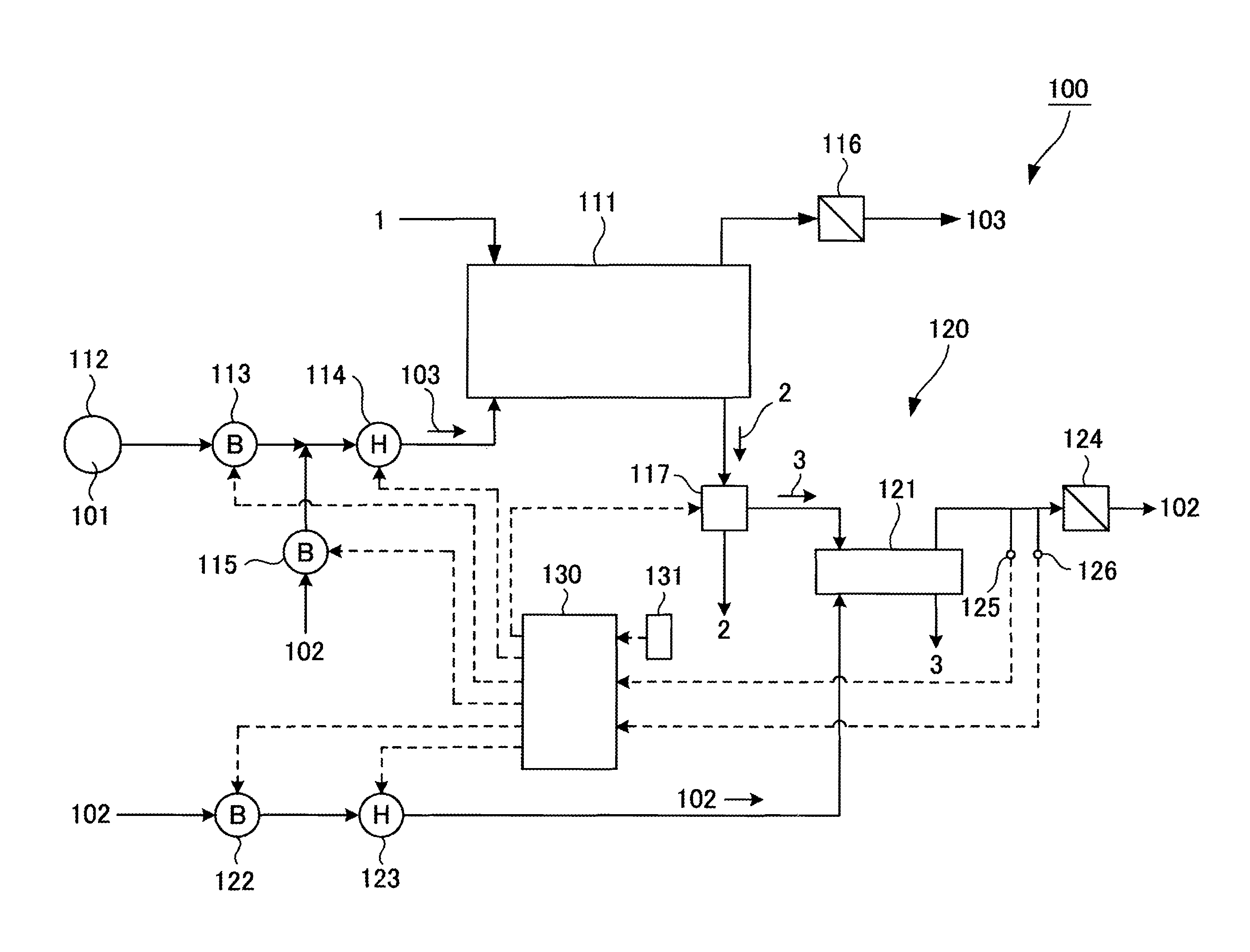
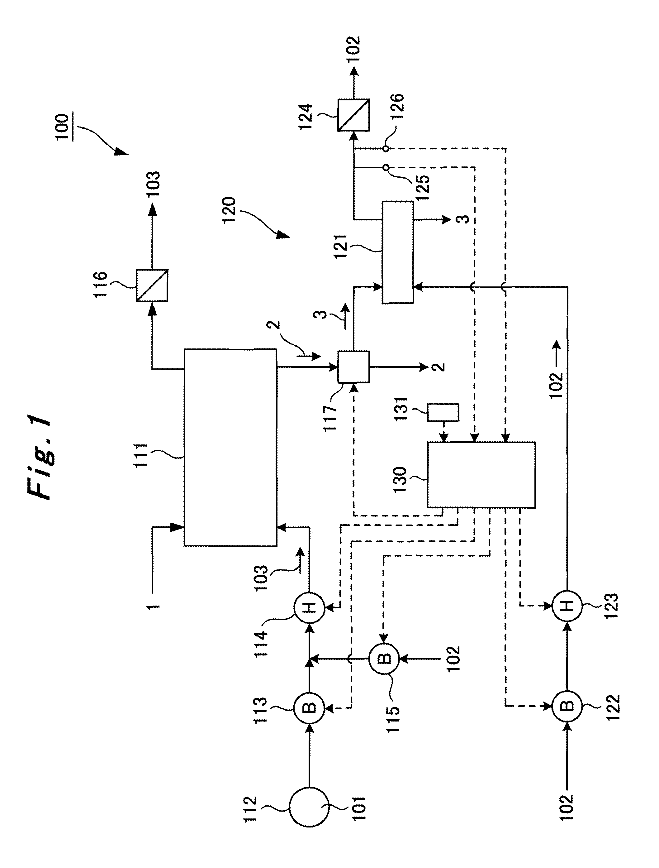
[0021]As shown in FIG. 1, a nitrogen gas supply source 112, which is an inert gas supply source, is connected to a lower portion of a treatment apparatus body 111 via a blower 113 and a heater 114. Pyrolyzed coal 1, coal obtained by drying and pyrolyzing low grade coal, is supplied to the inside of the treatment apparatus body 111 through an upper portion thereof. A blower 115 configured to supply air 102 is connected between the blower 113 and the heater 114.

[0022]In other words, operating the blowers 113 and 115 makes it possible to heat a treatment gas 103 with the heater 114 and supply the treatment gas 103 to the inside of...


PUM

PropertyMeasurementUnit
temperatureaaaaaaaaaa
temperature Ttaaaaaaaaaa
temperature Tcaaaaaaaaaa

Abstract

The coal deactivation apparatus including: a separating device that separates out a portion of the beneficiated coal deactivated in the main treatment apparatus; a main evaluation apparatus into which the sample of the beneficiated coal separated out by the separating apparatus is supplied; a blower and heater that supply air at the evaluation temperature to the main evaluation apparatus; a temperature sensor that detects the temperature of the air that has heat-treated the sample in the main evaluation apparatus; and a control unit that, when the temperature of the air is at or below the lower limit on the basis of information from the temperature sensor, determines whether or not the temperature of the process gas is at or below the lower limit and if the process gas temperature exceeds the lower limit, controls the heater to reduce the temperature of the process gas by a prescribed value.

Description

TECHNICAL FIELD[0001]The present invention relates to a coal inactivation system configured to inactivate coal by heating the coal with a treatment gas containing oxygen.BACKGROUND ART[0002]Low rank coals (low grade coals), coals having a high moisture content such as lignite and sub-bituminous coals, are abundant. However, the heating value per unit weight is small, and the transportation efficiency is low. Accordingly, such coal is heated and dried to increase the heating value per unit weight, and also compression-molded to improve the handling.[0003]Meanwhile, the low grade coal thus heated is likely to adsorb water. In addition, a carboxyl group and the like are released from the surface, and radicals and the like are generated on the surface. This increases the surface activity, promoting a reaction with oxygen in air. As a result, spontaneous combustion may occur due to a reaction heat generated by the reaction.[0004]For this reason, for example, the following inactivation tr...

Claims


Application Information

Patent Timeline
Patent Type & Authority Patents(United States)
IPC IPC(8): C10L9/08C10B57/08
CPCC10L9/083C10B57/08C10L9/08C10L2290/58C10L2290/60Y02E50/10
Inventor SATO, KEIICHITANIZAKI, KEIJIOMOTO, SETSUO
Owner MITSUBISHI HEAVY IND LTD
Why Eureka
Try Eureka