Pneumatic clutch with improved friction member

a technology of friction member and fan, which is applied in the direction of fluid actuated clutches, clutches, non-mechanical actuated clutches, etc., can solve the problems of reducing efficiency, limiting the reduction of drive assembly, and not always desirable for such fan assemblies to be run continuously, so as to achieve less expensive and increase the effect of performance without increasing size or shap

Inactive Publication Date: 2016-03-22
BORGWARNER INC
View PDF27 Cites 0 Cited by
  • Summary
  • Abstract
  • Description
  • Claims
  • Application Information

AI Technical Summary

Benefits of technology

[0006]It is therefore an object to the present invention to provide an clutch assembly with increased performance without increasing size or shape. It is further an object of the present invention to provide a clutch assembly which is less expensive.
[0007]In accordance with the objects of the present invention, clutch assemblies are provided with improved friction members, less expensive friction members, and increased performance. A central piston chamber is positioned therein and feeds a pressure chamber. A translatable clutch piston is in communication with the pressure chamber and is movable between a piston neutral and activated positions in response to air pressure fed into the pressure chamber. A rotating drive shaft is positioned within the clutch housing. A cone clutch element is moved from a clutch engaged position against a friction member to a clutch disengaged position in response to the translatable clutch piston moving between the neutral and activated positions. The cone clutch element engages the rotating drive shaft when in the clutch engaged position. A clutch spring biases the cone clutch element into the clutch engaged position with a clutch engagement force.
[0008]New less expensive friction ring members are provided for engagement with the cone clutch element. The friction ring member can consist of a solid or hollow inorganic core on which the friction material is molded or otherwise applied to form a layer on the core with or without air gaps in the friction material. The core of the friction ring can also be a metal stamping or formed element having a V-shape with friction liner material on the outer and inner diameters. In another embodiment, the friction ring can be replaced with a bent retaining plate held in place by a fastener and having the mating surface covered with friction material. With any of these new friction ring embodiments, the clutch element can be provided with an extended radial length. This can provide a clutch with greater strength and greater torque and capacity, without increasing or changing the exterior size or shape of the clutch assembly.
[0009]With a stronger clutch with more torque, the clutch assembly can be used in more applications and with larger cooling fans.

Problems solved by technology

It is not always desirable for such fan assemblies to be run continuously.
Additionally, continuous operation when unnecessary places an non-required draw on the engine and thereby reduces efficiency.
An issue with these fan assemblies and associated clutch assemblies stems from their location within the engine compartment.
However, fan clutch drives are commonly dimensionally constrained by the internal workings of the clutch which limits reduction of the drive assembly.
This dimensional constraint, especially realized in clutch length, limits the applications wherein a pneumatic clutch can be utilized.

Method used


Image

  • Pneumatic clutch with improved friction member
  • Pneumatic clutch with improved friction member
  • Pneumatic clutch with improved friction member

Examples


first embodiment

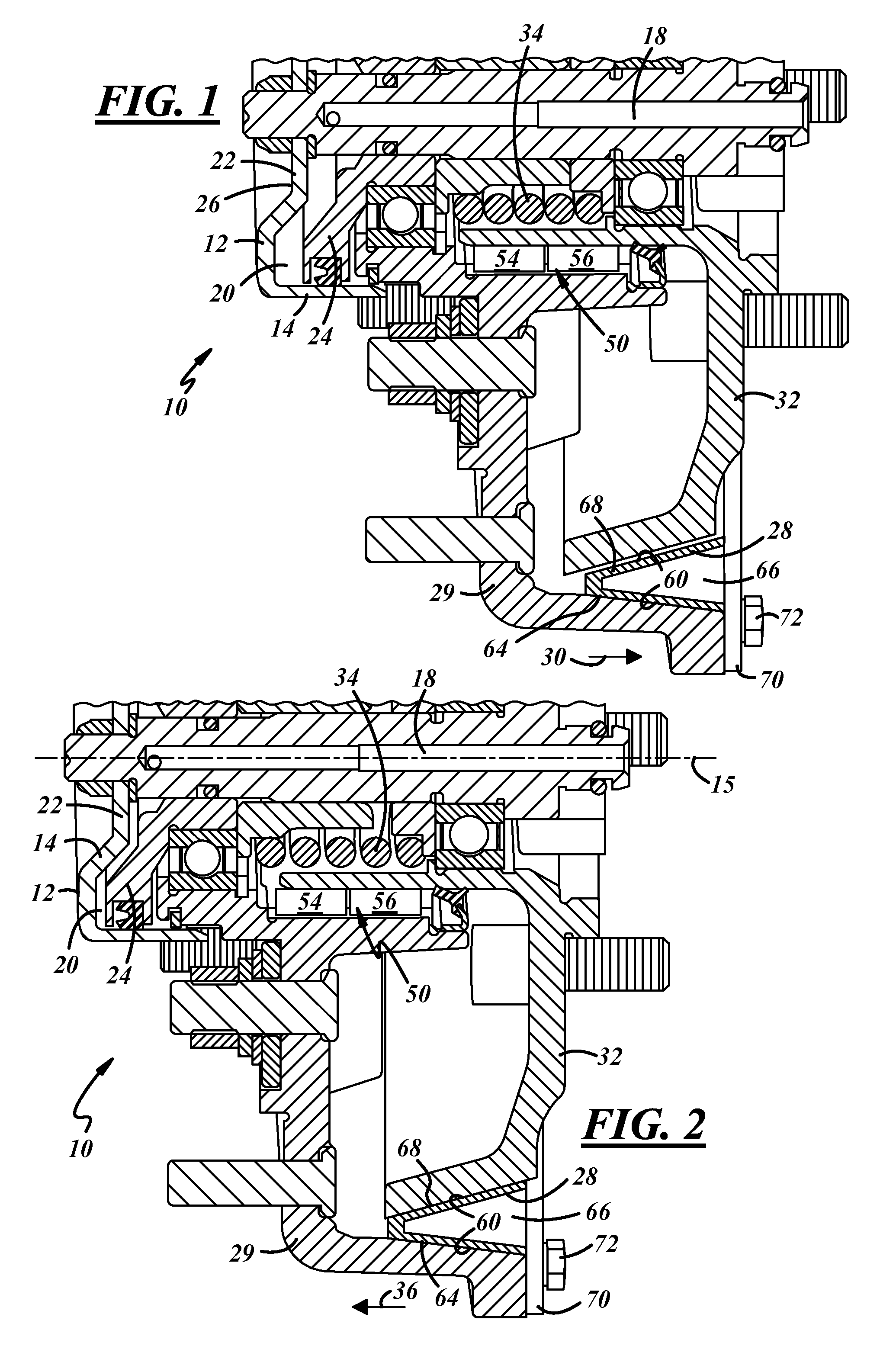
[0017]Referring now to FIG. 1 which is a cone clutch fan drive assembly 10 in accordance with the present invention. The fan drive assembly 10 includes a clutch assembly 12 having a clutch housing 14. The present invention provides novel and valuable improvements to the clutch assembly 12 that reduces the cost of the assembly and can provide a stronger assembly with more torque and capacity without changing the exterior size and shape of the assembly.

[0018]The components and operation of the clutch assembly 12 are similar to the clutch assembly shown and described in U.S. patent application Ser. No. 10 / 905,505 entitled “Reduced Axial Length Airactuated Cone Clutch Fan Drive” and filed on Jan. 7, 2005, and patent application Ser. No. 11 / 675,156 filed on Feb. 15, 2007. Thus, many of the components contained in the clutch assembly utilized herewith, as well as the basic operation thereof, do not need to be discussed and reference is made to those two other applications for a further di...

second embodiment

[0028]FIGS. 3 and 4 depict the invention. In this embodiment, the cone shaped friction member 128 is made of a formed piece of metal material 130 with a hollow center area 132 and pieces of friction liner material 134 secured to the inner 136 and outer 138 surfaces of the member 128. The friction material 134 can be a 360° continuous strip of material, or it can be segmented and made of a plurality of pieces or sections spaced on the surfaces 136 and 138. In this regard, any conventional friction liner material of any conventional size and shape can be utilized with this embodiment of the invention.

[0029]Similar to the embodiment of friction member 28 described above with reference to FIGS. 1 and 2, the construction of this second embodiment of friction member 128 can be made smaller than the solid rings of friction material provided in the prior art pneumatic clutches. This allows the drive shaft member 32 to have an increased diameter thereby providing a clutch assembly with incre...

third embodiment

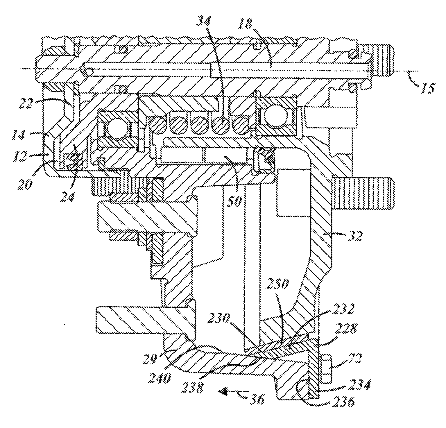
[0030]the invention is shown in FIGS. 5 and 6. In this embodiment, the cone shaped friction member 228 is made of a bent piece of metal material 230, preferably of steel or aluminum. The metal material also has a generally V-shape, but has one leg member 232 positioned inside the housing 29 and the second leg member 234 positioned on the outer surface 236 of the housing. The friction member 228 is held in place by one or more fasteners 72, such as bolts. A separate retaining plate is not needed.

[0031]The inner end 238 of member 228 is formed at an angle such that the end contacts flush with the inner surface 240 of the housing 29. This provides strong support for the friction member and prevents the end from moving or sliding along, the surface 240 when the clutch is engaged.

[0032]A friction liner material 250 is securely affixed to the inner surface of the inner leg member 232. The friction liner can be made of any conventional friction liner material and be secured in any conventi...


PUM


Abstract

A clutch assembly comprising a clutch housing, a central piston chamber positioned therein and a translatable clutch piston movable between a piston neutral and activated positions in response to air pressure. A rotating drive shaft member is positioned within the clutch housing. A cone clutch friction member is moved from a clutch engaged position to a clutch disengaged position in response to the translatable clutch piston moving between the piston neutral and activated positions. The cone clutch friction member engages the rotating drive shaft when in the clutch engaged position. A clutch spring biases the cone clutch friction member into the clutch engaged position with a clutch engagement force. The cone clutch friction member comprises a V-shaped member with a hollow or solid core, or a bent metal member. Friction material is positioned on at least the surfaces which engage and make contact with the rotating drive shaft member.

Description

TECHNICAL FIELD[0001]The present invention relates generally to a fan clutch and more particularly to a fan clutch which has more torque and capacity and which is less expensive to manufacture.BACKGROUND OF THE INVENTION[0002]Vehicle engines commonly utilize cooling assemblies to remove excess heat from the engine and maintain an optimal operating temperature. The cooling assembly pumps a coolant through the engine and other components in order to control engine temperature. Heat generated within the engine and other components is absorbed by the coolant and dispersed into the surrounding atmosphere through the use of a radiator. In order to improve dispersal by the radiator, it is common to utilize fan assemblies to draw or force air past the radiator to assist in temperature transmission.[0003]It is not always desirable for such fan assemblies to be run continuously. At times, it is desirable for the temperature within the coolant to increase rather than decrease. Additionally, co...

Claims


Application Information

Patent Timeline
Patent Type & Authority Patents(United States)
IPC IPC(8): F16D25/06F16D25/08F16D25/0632
CPCF16D25/082F16D25/0632
Inventor SETTINERI, SAMUEL, E.
Owner BORGWARNER INC
Why Eureka
Try Eureka