Forced-flow steam generator

a technology of forced-flow steam and generator, which is applied in the direction of machines/engines, mechanical equipment, light and heating equipment, etc., can solve the problems of equalization of water and steam content, insufficient heat dissipation, etc., and achieve the effect of avoiding restrictions in the operation of power plants and sufficient heat dissipation

Active Publication Date: 2016-03-22
SIEMENS ENERGY GLOBAL GMBH & CO KG
View PDF18 Cites 0 Cited by
  • Summary
  • Abstract
  • Description
  • Claims
  • Application Information

AI Technical Summary

Benefits of technology

[0012]In an advantageous embodiment the respective restrictor device is arranged at the upper outlet of the surrounding wall. Such an arrangement makes a particularly simple construction of the steam generator possible and at the same time permits the retrofitting of existing systems having the aforementioned problem.
[0013]Advantageously, the restrictor device is designed as a simple aperture. This permits a particularly simple local reduction of the nominal size of the steam generator pipe concerned and as a result, a simple increase in the friction pressure drop. This measure also permits particularly simple installation of the restrictor device in order to reduce the natural circulation characteristic.
[0019]The advantages obtained with the invention comprise in particular ensuring sufficient heat dissipation in each pipe, and as a result inadmissibly high temperatures which might lead to damage to the pipe wall being avoided, through the arrangement of one restrictor device in the steam generator pipes of a forced-flow steam generator arranged downstream of the passage collector. This measure is based on the knowledge that a significant natural circulation characteristic which is reduced by the arrangement of restrictors is also present in a forced-flow steam generator. Lastly, restrictions in the operation of a power plant are avoided as a result.

Problems solved by technology

Insufficient heat dissipation occurs if the mass flow of the steam generator pipe concerned is too low.
Although the passage collector should bring about a certain equalization between the pipes downstream of it in order to mitigate this effect, it has however been recognized that although the passage collector brings about complete pressure equalization, it does not bring about complete mixing of the incoming flow medium, which would result in equalization of the water and steam content in the steam generator pipes downstream of it.

Method used


Image

  • Forced-flow steam generator
  • Forced-flow steam generator
  • Forced-flow steam generator

Examples


Embodiment Construction

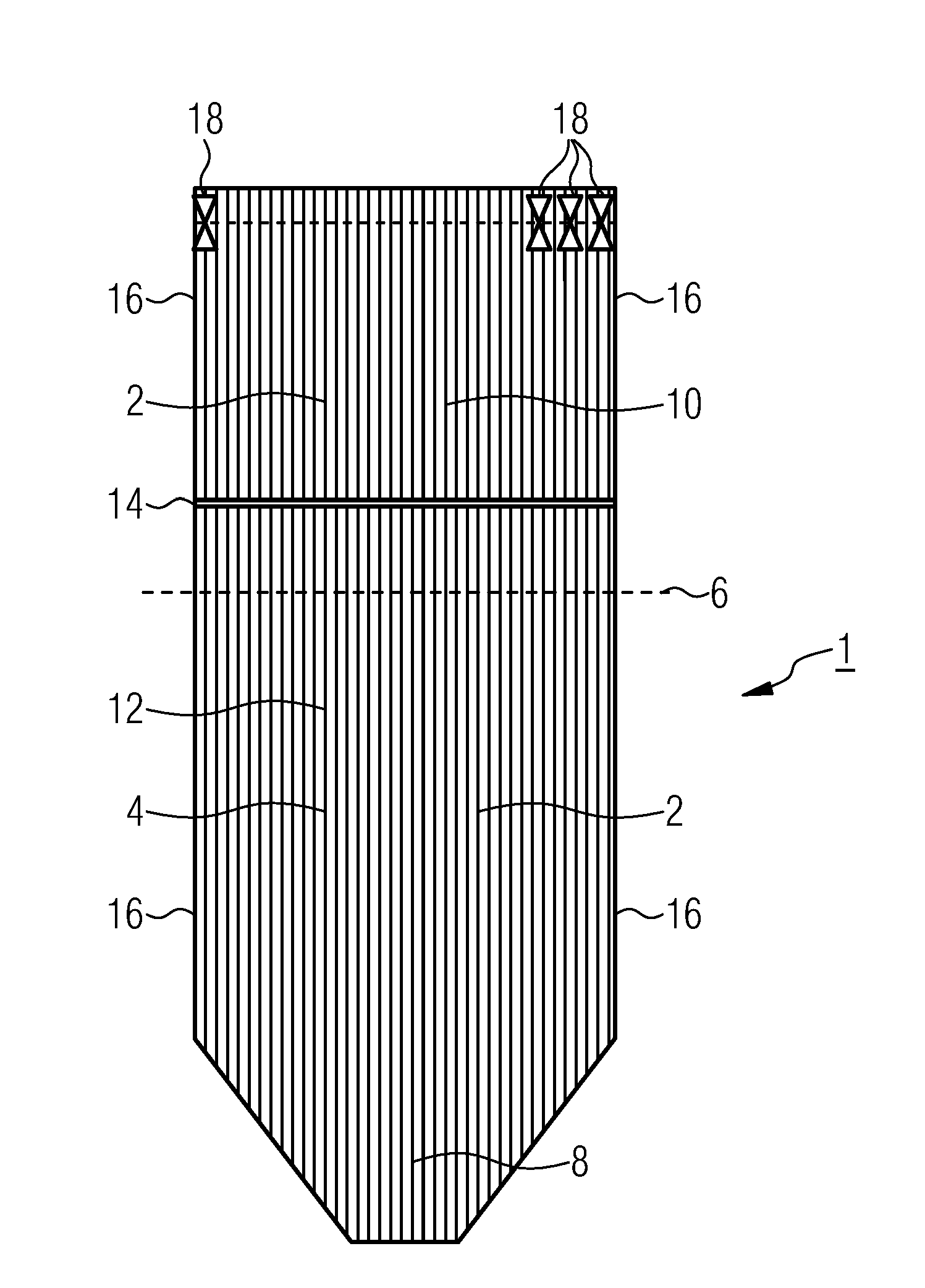
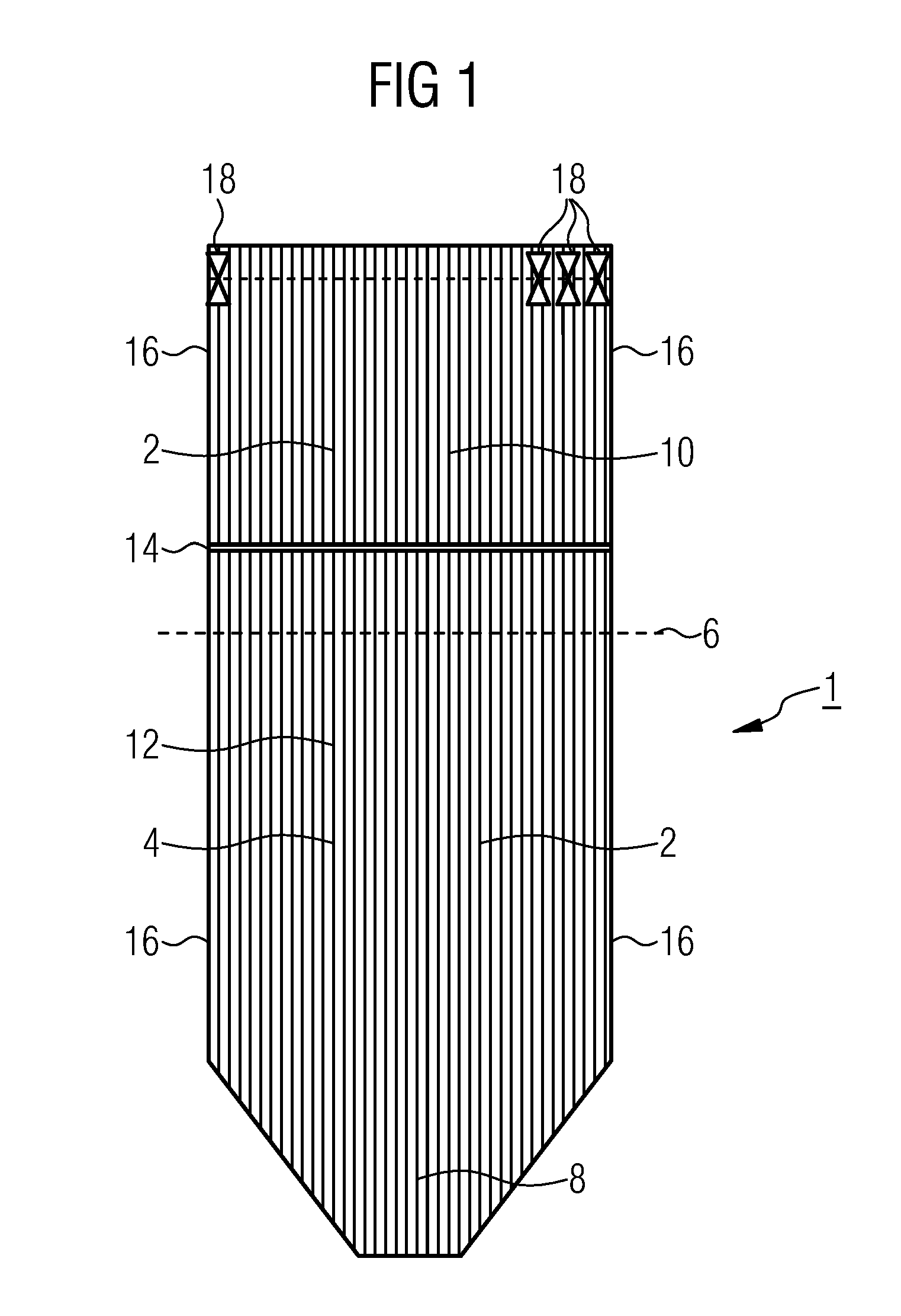
[0024]FIG. 1 is a diagram of a fossil-fuel fired, vertically piped forced-flow steam generator 1 in accordance with the invention. The forced-flow steam generator 1 comprises a surrounding wall 4 formed from steam generator pipes 2 which are welded in a gas-tight fashion. The surrounding wall 4 has an essentially rectangular horizontal cross-section 6. A combustion chamber 8 with a number of burners (not shown in more detail) for the combustion of a fossil fuel and which supply the heat to the steam generator pipes 4 is arranged in the lower section of the forced-flow steam generator 1.

[0025]The surrounding wall 4 is divided into an upper section 10 and a lower section 12, wherein the sections 10 and 12 are connected to each other via a passage collector 14. The pipework in the lower section 12 is arranged vertically here, but can also be arranged in a spiral shape circumferentially around the surrounding wall. The passage collector 14 collects all the flow medium emerging from the ...


PUM


Abstract

A forced-flow steam generator includes first and second steam generator pipes which form a surrounding wall, wherein the first and second steam generator pipes are welded in a gas-tight fashion and are traversable by flow in a vertical direction. A passage collector is arranged within the surrounding wall, wherein the passage collector connects the first steam generator pipes with the second steam generator pipes. The first steam generator pipes are connected at an outlet side to an inlet side of the second steam generator pipes, wherein the second steam generator pipes are connected in series with the first steam generator pipes. Each of the second generator pipes has a restrictor device. Further, a power plant with a forced-flow steam generator is provided.

Description

CROSS REFERENCE TO RELATED APPLICATIONS[0001]This application is the US National Stage of International Application No. PCT / EP2011 / 059930 filed Jun. 15, 2011, and claims the benefit thereof. The International Application claims the benefits of German Patent Application No. 10 2010 038 883.1 DE filed Aug. 4, 2010. All of the applications are incorporated by reference herein in their entirety.FIELD OF INVENTION[0002]The invention relates to a forced-flow steam generator having a surrounding wall formed from steam generator pipes which are welded in a gas-tight fashion and traversable by flow in the vertical direction, in which within the surrounding wall there is arranged a passage collector by means of which the outlet side of a first multiplicity of steam generator pipes in parallel configuration is connected at the flow medium side to the inlet side of a second multiplicity, in series configuration with and downstream of the first multiplicity, of steam generator pipes in parallel ...

Claims


Application Information

Patent Timeline
Patent Type & Authority Patents(United States)
IPC IPC(8): F01K23/06F22B37/74F01K7/16F22B29/02F22B21/36F22B21/34F22B29/06
CPCF22B29/062F01K7/16F22B21/34F22B21/366F22B29/02F22B37/74F22B21/36
Inventor BRODE.BETA.ER, JOACHIMBRUCKNER, JANEFFERT, MARTINFRANKE, JOACHIMSCHULZE, TOBIAS
Owner SIEMENS ENERGY GLOBAL GMBH & CO KG
Why Eureka
Try Eureka