Wind turbine main bearing

a technology of main bearing and wind turbine, which is applied in the direction of liquid fuel engines, vessel construction, marine propulsion, etc., can solve the problems of infrequent start-up or shut-down procedures, different operating conditions, etc., and achieve the effects of reducing load, convenient removal, insertion or maintenance, and convenient installation

Active Publication Date: 2016-03-29
SIEMENS GAMESA RENEWABLE ENERGY AS
View PDF16 Cites 9 Cited by
  • Summary
  • Abstract
  • Description
  • Claims
  • Application Information

AI Technical Summary

Benefits of technology

[0014]Advantageously, therefore, the inventive fluid bearing for a wind turbine provides a more suitable type of bearing, being less susceptible to bearing failure than the conventional roller bearing, while being considerably easier to maintain. A pad of the fluid bearing, for example, can relatively easily be removed or inserted without having to disassemble the drive train, which must be done in the case of roller bearings in order to access the bearings.
[0033]In a further preferred embodiment of the wind turbine according to the invention, the wind turbine comprises a lifting arrangement such as a jack for raising a relevant part such as the main shaft to reduce the load on the main bearing in order to facilitate removal, insertion or maintenance of a bearing pad in the lower region of the bearing housing. Such a simple jack, as the skilled person will appreciate, is quite easily installed in a wind turbine Nacelle housing. Using such a jack, the main shaft or rotor can be lifted and fixed to support the load and hold the shaft stable. Then, since the bearing pads are no longer under any load, they can easily be replaced in one operation. If there are three or more pads in a ring arrangement, one pad at a time can be removed during maintenance while the remaining pads continue to support the shaft or rotor. Use of at least three pads in a ring arrangement is advantageous, since at least two pads are then available to support the shaft while a bearing pad is removed. A bearing pad in the upper region of the bearing housing may be easily removed without raising the main shaft, since the weight of the shaft is borne by the pads in the lower region when the shaft is not rotating.

Problems solved by technology

However, turbines used in these fields of application are high-speed and low-load applications, i.e. the rotor rotates at a high speed of hundreds of rpm—while the load exerted on the main bearing is generally low and constant, due to the more constant nature of water flow, and such turbines very infrequently undergo start-up or shut-down procedures.
In a wind energy converter, however, operating conditions are very different, as outlined in the introduction—comprising low rotational speeds, high loads, and frequent start-up and shut-down.

Method used


Image

  • Wind turbine main bearing
  • Wind turbine main bearing
  • Wind turbine main bearing

Examples


Embodiment Construction

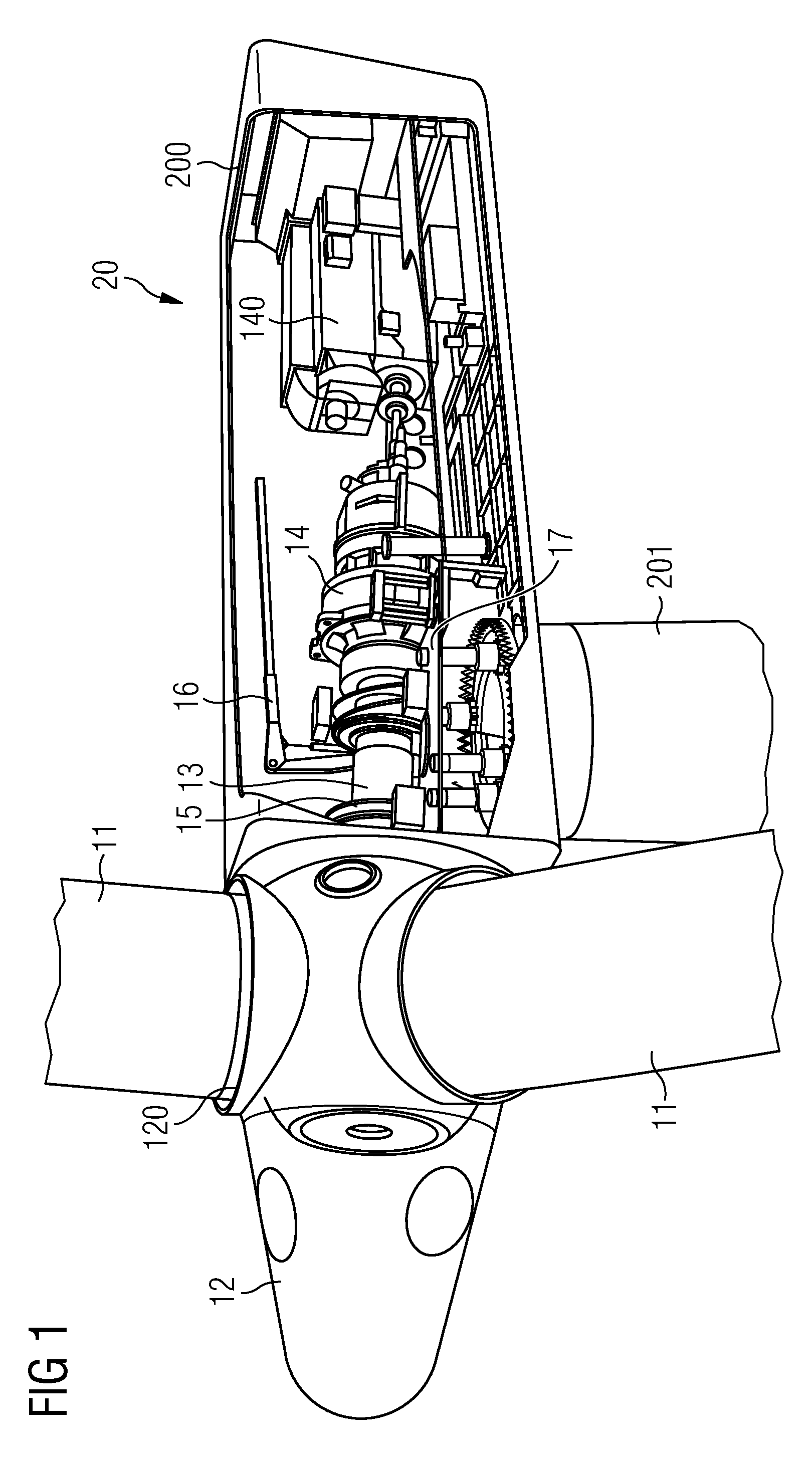
[0048]FIG. 1 shows a schematic rendering of the basic elements of an exemplary prior art wind turbine 20, in this case a Nacelle arrangement of a wind turbine with a drive train and a gearbox in a housing 200 carried by a tower 201. Only the relevant elements are shown for the sake of clarity.

[0049]The blades 11 of the wind turbine 20, usually but not necessarily three in number, are affixed to a hub 12 or spinner 12 by means of a pitch bearing 120 with which the blades 11 can be furled, for example during storm conditions. In normal operation, wind exerts pressure on the blades 11, which cause the spinner 12 and the attached main shaft 13 to rotate. The rotational energy is converted into electrical energy using a gearbox 14 and generator 140. The details of the energy conversion are not of relevance here and therefore will not be explained in further detail. The drive assembly comprising the main shaft 13, gearbox 14 etc. is mounted on a Nacelle bedplate 17. The dimensions of the ...


PUM

PropertyMeasurementUnit
diameteraaaaaaaaaa
diameteraaaaaaaaaa
diameteraaaaaaaaaa

Abstract

A wind turbine main bearing realized to bear a shaft of a wind turbine, which shaft is caused to rotate by a number of blades connected to the shaft is disclosed. The wind turbine main bearing includes a fluid bearing with a plurality of bearing pads arranged about the shaft. Also disclosed is a wind turbine with a number of blades connected to a shaft and realized to rotate the shaft, which wind turbine includes as main bearing a wind turbine main bearing. Further described is a method of performing maintenance on a wind turbine, including the steps of halting a rotation of the shaft, operating a lifting arrangement to raise the shaft, and removing a bearing pad of the wind turbine main bearing from the bearing housing of the wind turbine main bearing.

Description

CROSS REFERENCE TO RELATED APPLICATIONS[0001]This application is U.S. National Stage of International Application No. PCT / EP2009 / 062483, filed Sep. 28, 2009 and claims the benefit thereof. The International Application claims the benefits of U.S. provisional application No. 61 / 224,525 DE filed Jul.10, 2009. All of the applications are incorporated by reference herein in their entirety.FIELD OF THE INVENTION[0002]The invention describes a wind turbine main bearing. The invention further describes a wind turbine with a wind turbine main bearing and a method of performing maintenance on a wind turbine.BACKGROUND OF THE INVENTION[0003]Wind turbines used in wind energy converters (also called wind generators) for the production of electric power make a valuable contribution towards obtaining energy from renewable sources. Wind energy converters can be onshore, i.e. land-based, or offshore, i.e. constructed in a coastal area. Onshore wind turbines are surpassed in performance by offshore ...

Claims


Application Information

Patent Timeline
Patent Type & Authority Patents(United States)
IPC IPC(8): F03D80/70
CPCF03D11/0008Y02B10/30Y02E10/722F03D80/70F16C17/03F16C2300/14F16C2360/31F16C35/02Y10T29/49238F16C2237/00F05B2240/50Y02E10/72
Inventor GUERENBOURG, PIERRE-ANTOINENEW, NIGELSTEGE, JASONTHOMSEN, KIM
Owner SIEMENS GAMESA RENEWABLE ENERGY AS
Why Eureka
Try Eureka