
Propeller shaft

a technology of propeller shaft and shaft shaft, which is applied in the direction of shock absorbers, couplings, transportation and packaging, etc., can solve the problems of insufficient increase injury to passengers, and change in axial length, so as to reduce the shock transmission and reduce the injury to passengers

Active Publication Date: 2016-04-19
HYUNDAI MOTOR CO LTD
View PDF17 Cites 8 Cited by
  • Summary
  • Abstract
  • Description
  • Claims
  • Application Information

AI Technical Summary

Benefits of technology

[0016]Accordingly, the present invention has been made keeping in mind the above problems occurring in the related art and / or other problems, and the present invention is intended to provide a propeller shaft for a vehicle, in which an axial length is sufficiently changed in the event of a vehicle crash to sufficiently absorb impact energy resulting from a crash and thereby decrease shock transmitted to a vehicle body, thus reducing injury to a passenger to the maximum.
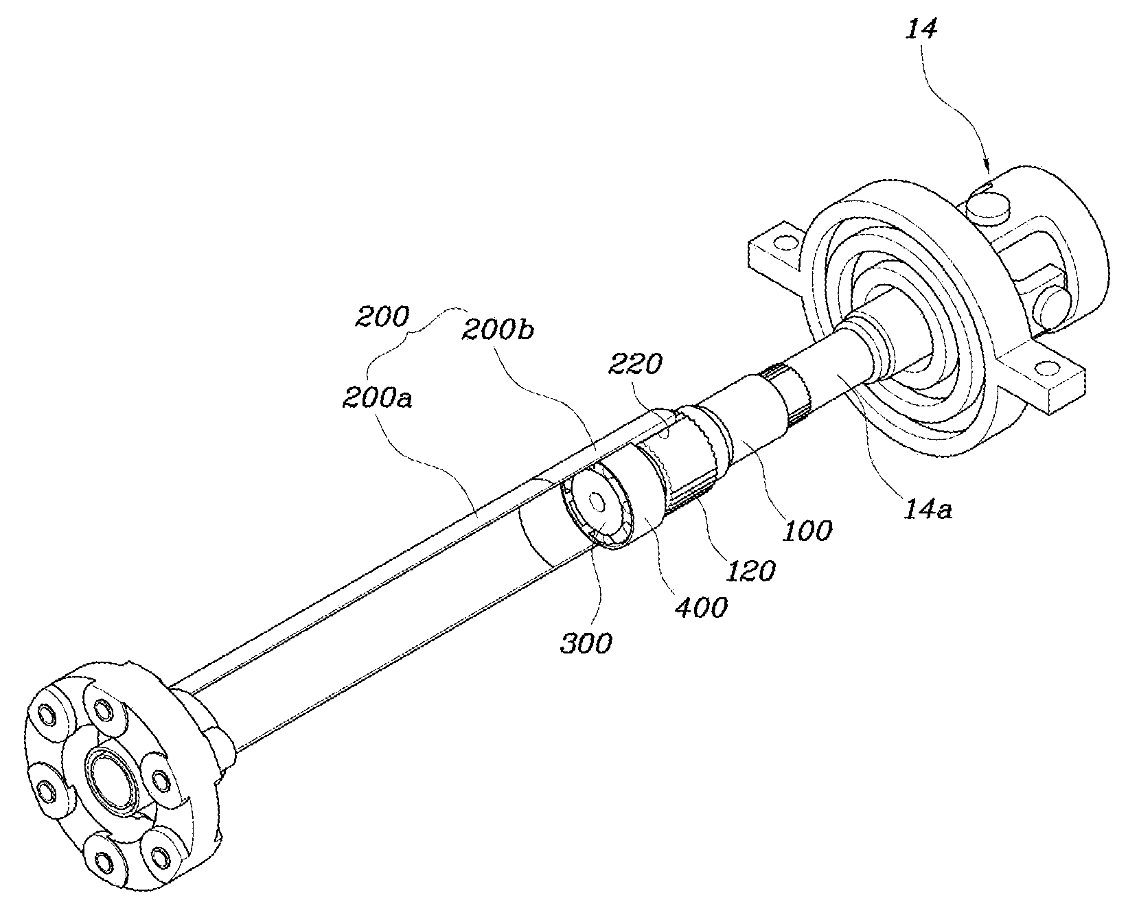
[0017]Various aspects of the present invention provide for a propeller shaft that may include: a shaft having on an outer circumference of an end thereof a plurality of locking protrusions for a spline coupling; a tube having, on an inner circumference thereof into which the shaft is inserted, a plurality of locking grooves, the locking grooves engaging with the locking protrusions to form the spline coupling; a dynamic damper provided inside the tube, disposed to correspond to the end of the shaft, and absorbing vibrations transmitted from a driving system; and a rubber stopper interposed between an outer circumference of the dynamic damper and the inner circumference of the tube to support the dynamic damper, and provided to correspond to the end of the shaft to limit sliding of the tube at normal times, the rubber stopper being broken by a pushing operation of the tube when an impact load greater than a collapse load of the rubber stopper acts on the rubber stopper, thus permitting the sliding of the tube.
[0021]As is apparent from the above description, the propeller shaft for the vehicle is advantageous in that the shaft and the tube slide axially to sufficiently change the axial length in the event of the vehicle crash, thus being capable of sufficiently absorbing impact energy resulting from the crash. Thereby, it is possible to decrease shocks transmitted to the vehicle body and reduce injury to a passenger to the maximum.
[0022]Moreover, the propeller shaft for the vehicle is advantageous in that vibrations transmitted from the engine driving system are reduced by the dynamic damper, thus preventing the propeller shaft from being damaged due to the vibrations and enhancing durability.

Problems solved by technology

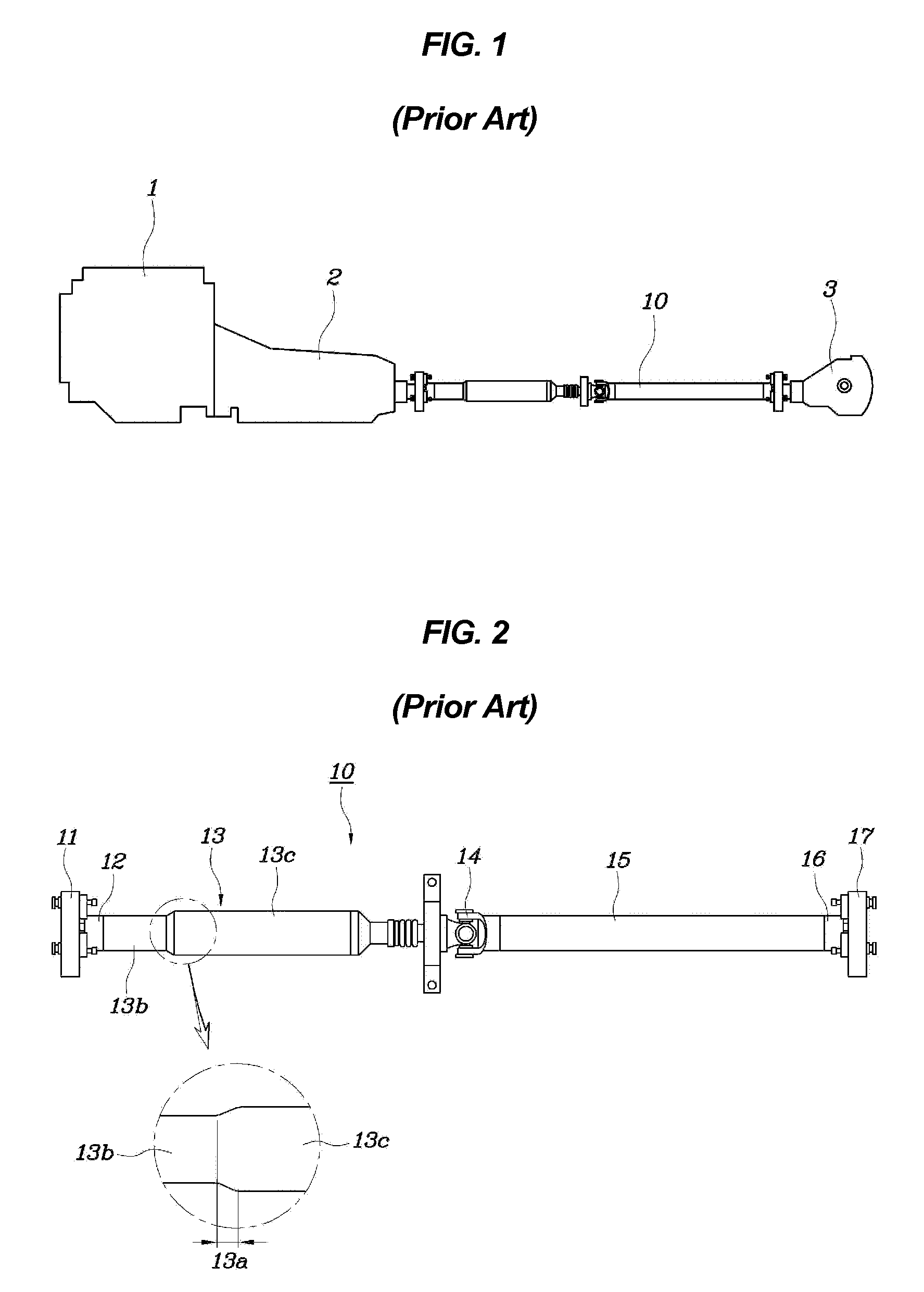
However, the conventional propeller shaft 10 is problematic in that its change in axial length is not sufficient due to a high collapse load in the event of a vehicle crash, so that the propeller shaft 10 cannot sufficiently absorb shocks and thereby increases injury to a passenger.
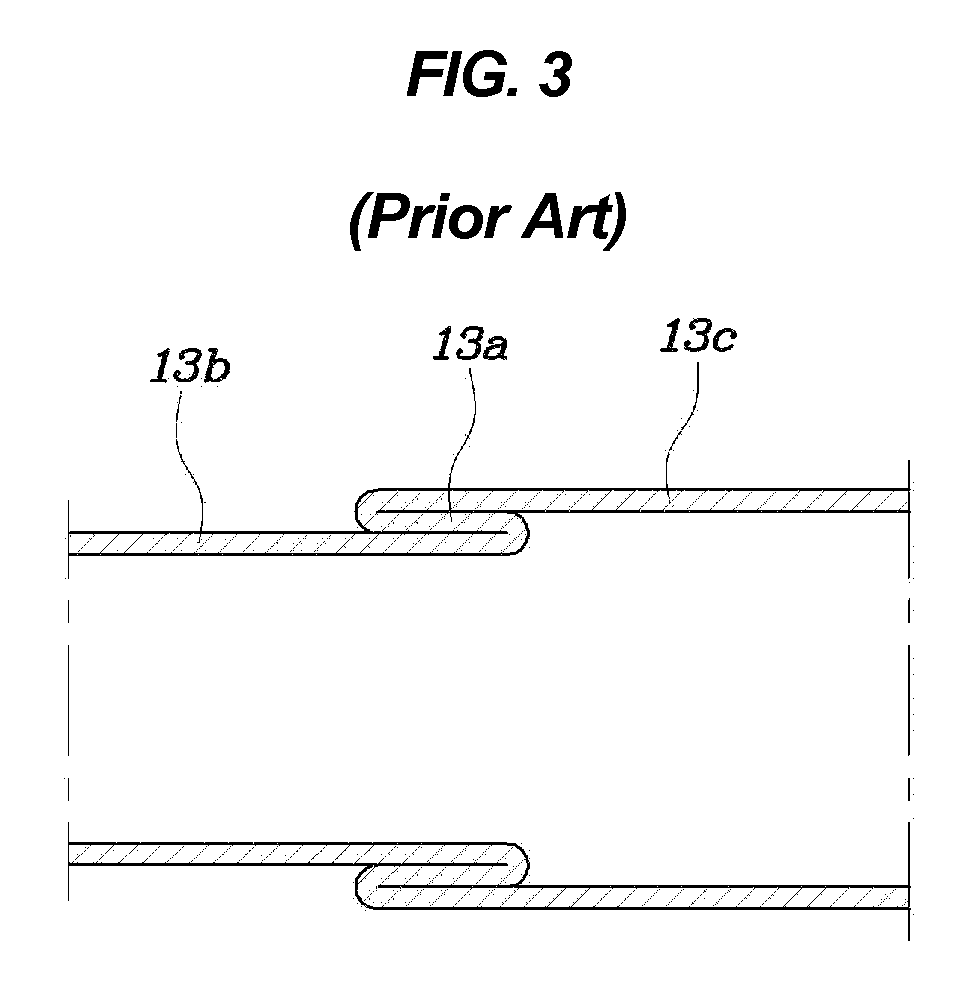
However, the conventional propeller shaft 10 is problematic in that a difference in diameter between the smaller diameter portion 13b and the larger diameter portion 13c is not large, so that a rearward moving amount of the smaller diameter portion 13b is small, and thus a change in axial length is not sufficient due to a high collapse load.
Consequently, it is impossible to sufficiently absorb impact energy.
In particular, injury to a passenger is increased due to the high deceleration of the vehicle.
However, such a change in diameter changes a basic strength or raises a new problem due to weight and a package with peripheral components.
However, such a method is not desirable because it causes a reduction in basic strength of the propeller shaft 10.

Method used


Image

  • Propeller shaft
  • Propeller shaft
  • Propeller shaft

Examples


Embodiment Construction

[0031]Reference will now be made in detail to various embodiments of the present invention(s), examples of which are illustrated in the accompanying drawings and described below. While the invention(s) will be described in conjunction with exemplary embodiments, it will be understood that present description is not intended to limit the invention(s) to those exemplary embodiments. On the contrary, the invention(s) is / are intended to cover not only the exemplary embodiments, but also various alternatives, modifications, equivalents and other embodiments, which may be included within the spirit and scope of the invention as defined by the appended claims.

[0032]A propeller shaft for a vehicle according to the present invention includes a front coupling 11 used to couple the propeller shaft with a transmission 2, a front yoke 12 coupled to the front coupling 11, a shaft 100 welded or fixed at one end thereof to the front yoke 12, a tube 200 coupled to the shaft 100 to form a spline coup...


PUM


Abstract

A propeller shaft for a vehicle includes a shaft having locking protrusions on an outer circumference, a tube having locking grooves on an inner circumference into which the shaft is inserted, the locking grooves engaging with the locking protrusions to form the spline coupling, a dynamic damper inside the tube to correspond to an end of the shaft and absorbing vibrations transmitted from a driving system, and a rubber stopper interposed between an outer circumference of the dynamic damper and the inner circumference of the tube to support the dynamic damper and correspond to the end of the shaft to limit sliding of the tube at normal times. The rubber stopper is broken by a pushing operation of the tube when an impact load greater than a collapse load of the rubber stopper acts on the rubber stopper, thereby permitting the sliding of the tube.

Description

CROSS-REFERENCE(S) TO RELATED APPLICATION[0001]The present application claims priority of Korean Patent Application Number 10-2013-0127441 filed on Oct. 24, 2013, the entire contents of which application are incorporated herein for all purposes by this reference.BACKGROUND OF INVENTION[0002]1. Field of Invention[0003]The present invention relates, in general, to propeller shafts for vehicles, and, more particularly, to a propeller shaft for a vehicle, which is intended to sufficiently absorb a change in axial length owing to a low collapse load in the event of a vehicle crash and thereby to sufficiently absorb impact energy, thus being capable of reducing injury to passengers to the maximum.[0004]2. Description of Related Art[0005]Generally, as shown in FIG. 1, a propeller shaft 10 installed at a rear-wheel-drive vehicle is a power transmission device that smoothly transmits a driving force of a power train including an engine 1 and a transmission 2 to a rear axle 3. The propeller s...

Claims


Application Information

Patent Timeline
Patent Type & Authority Patents(United States)
IPC IPC(8): F16D3/02F16C3/03F16D3/06F16D1/10F16F15/00
CPCF16D3/06F16C3/03F16D1/10F16D2001/103F16D2300/22F16F15/00Y10T464/50F16C3/02F16F7/108F16F15/10B60K17/22
Inventor CHOI, WON JUN
Owner HYUNDAI MOTOR CO LTD
Learn More