

Optical plate for lighting, and lighting apparatus using same
a technology of optical plates and lighting, applied in lighting and heating apparatus, instruments, semiconductor devices for light sources, etc., can solve the problems of reducing discomfort for viewers, and inability to meet the normal use of led lighting by single led diodes alone, so as to reduce the overall thickness of the optical plate for lighting. , to achieve the effect of efficient control of optical viewing angles
Active Publication Date: 2016-04-19
MIRAENANOTECH
View PDF37 Cites 2 Cited by
- Summary
- Abstract
- Description
- Claims
- Application Information
AI Technical Summary
Benefits of technology
Problems solved by technology
Due to the insufficient intensity of light, a single LED diode alone cannot fulfil the normal usage of LED lighting.
However, LED light has a strong characteristic of straight progression which makes each diode in the array independently visible, wherein incurs peripheral light leakage creating glare problems and eventually resulting discomfort to viewers.
However, as described above, LED light source has a prominent attribute of straight progression which is incapable of removing independent visibility of every single LED diode.
In spite of merits disclosed in Patent Document 6, wherein a light-diffusing member prevents each LED diode from being independently visible, the diffusion of light widens viewing angles and eventually intensifies glare problem.
Consequently, the overall thickness of the thickened optical plate for lighting became problematic.
Method used
View moreImage
Smart ImageViewing Examples

Examples
Embodiment Construction
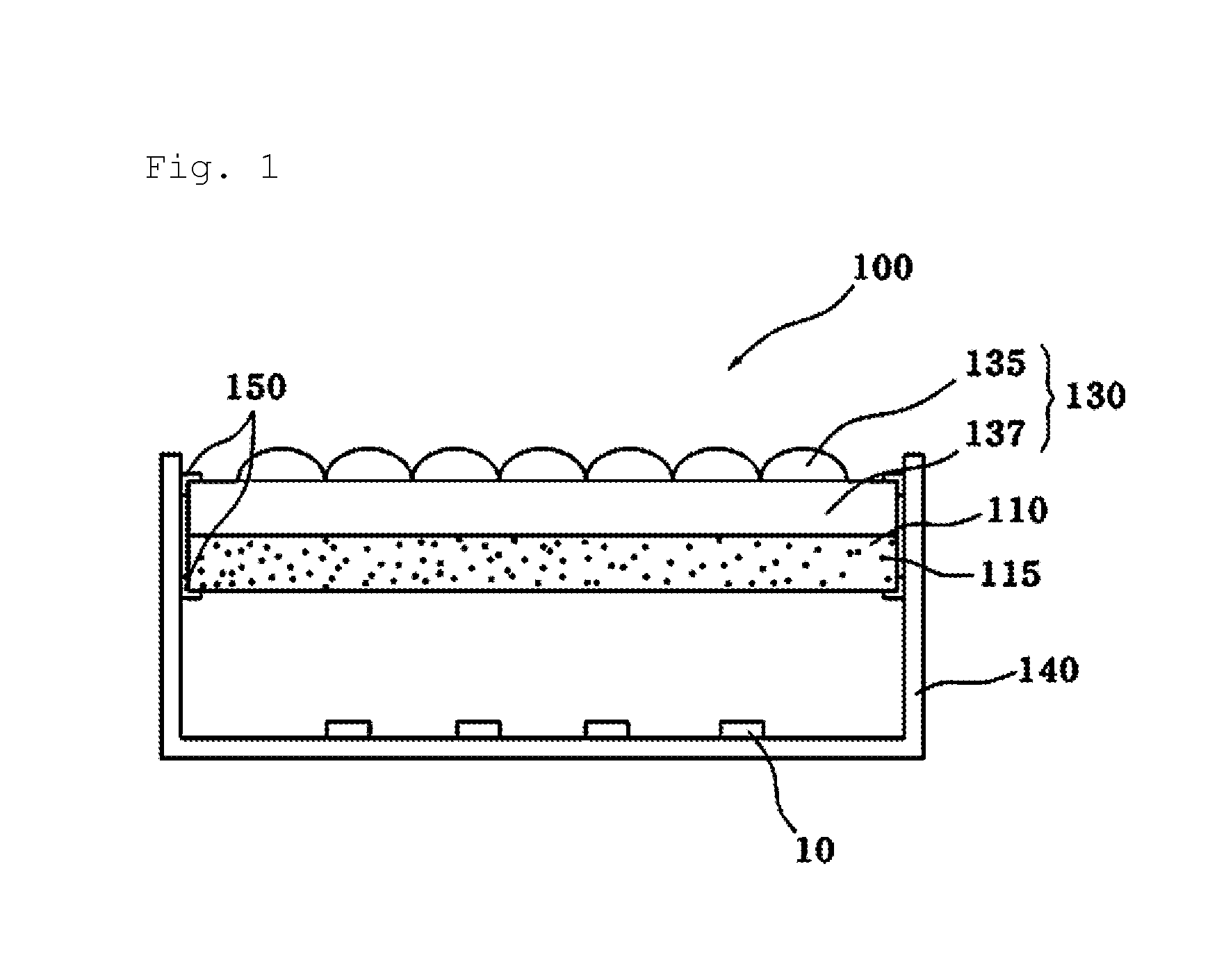
[0083]10, 720 LED
[0084]100 conventional lighting apparatus
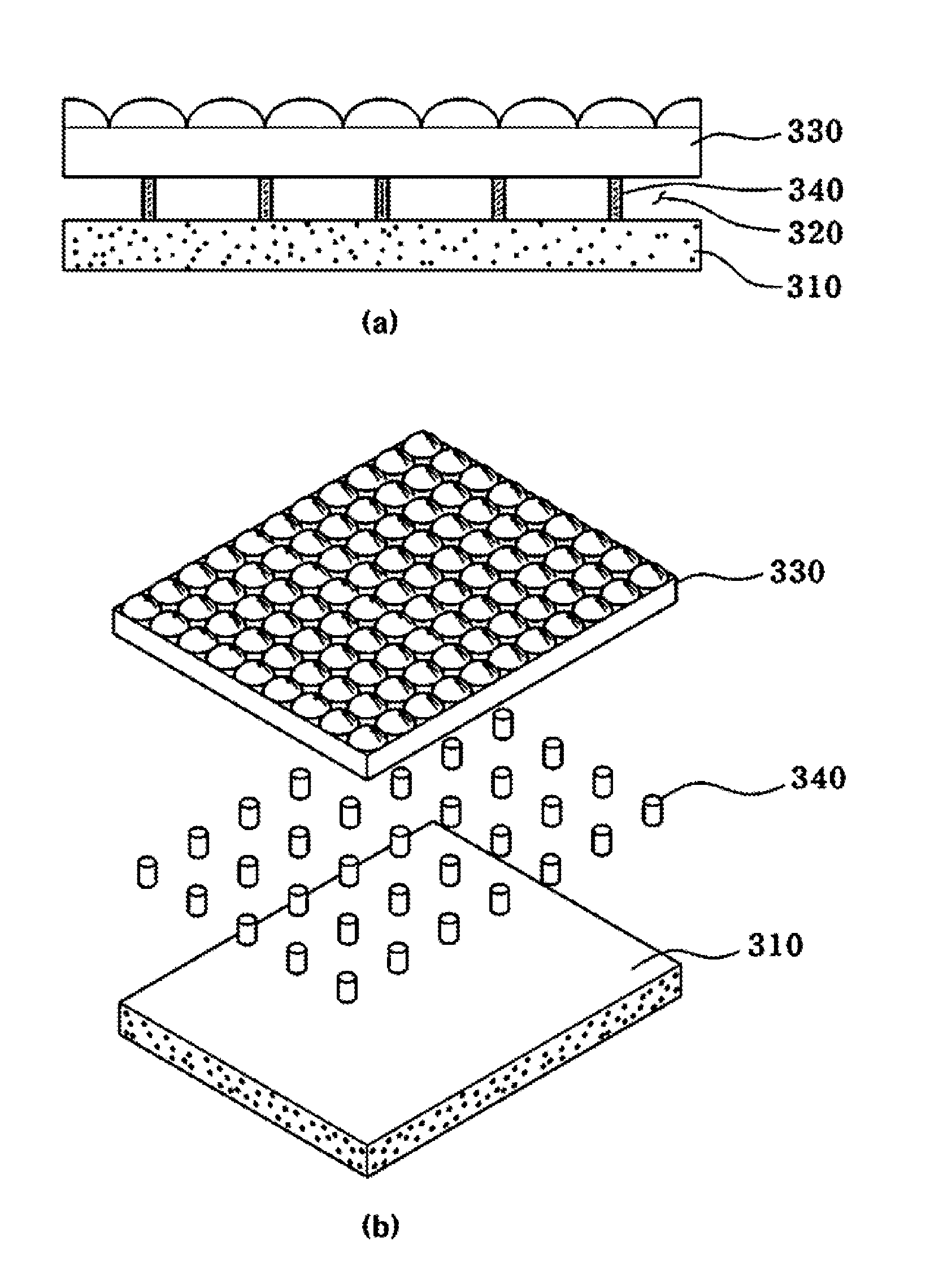
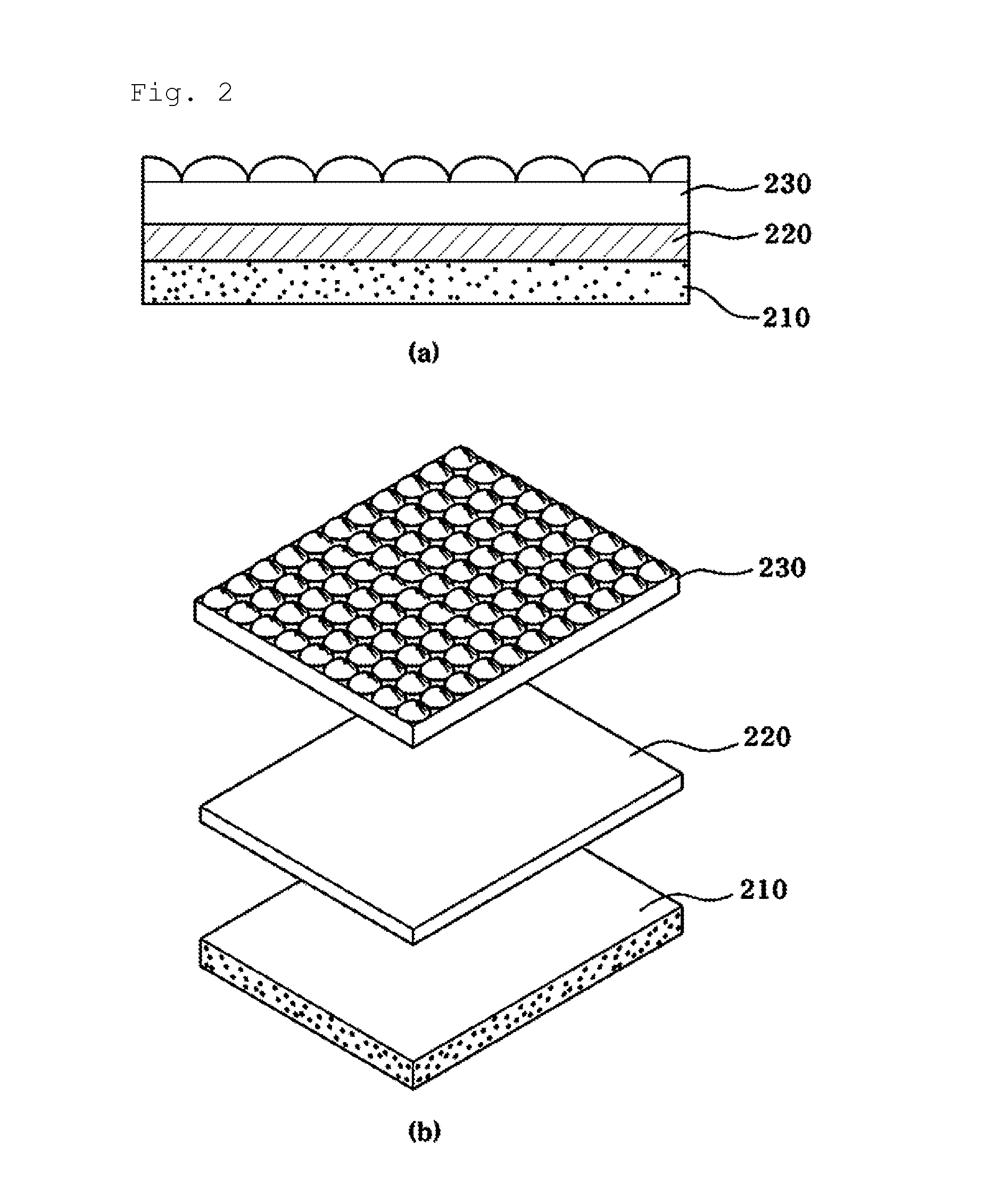
[0085]110, 210, 310, 810 light-diffusing member
[0086]115, 815 diffusing particle
[0087]130, 230, 330, 830 optical viewing angle adjusting member
[0088]135, 835 pattern layer
[0089]137, 837 base layer
[0090]140, 840 frame
[0091]150, 850 supporting member
[0092]220, 820 transmission layer
[0093]320 air layer
[0094]340 spacer
[0095]700, 800 direct-lit type lighting apparatus
[0096]710 optical plate for lighting
[0097]750 edge-lit type lighting apparatus
[0098]760 light guide plate
[0099]770 Cold Cathode Fluorescent Lamp (CCFL)
Login to View More PUM
 Abstract
The present invention relates to an optical plate for lighting capable of improving the brightness of light emitted from a light source and adjusting a viewing angle to alleviate side glare phenomenon. The present invention also relates to a lighting. The purpose of the present invention is to provide a structure in which a light-diffusing member and an optical viewing angle adjusting member can independently function; an integrated optical plate for lighting, wherein the thickness of the optical plate for lighting is reduced by the lamination of a light-diffusing member, a transmission layer, and an optical viewing angle adjusting member; a lighting apparatus using thereof. In order to achieve this purpose, the technical properties of an optical plate for lighting according to the present invention have a transmission layer between a light-diffusing member and an optical viewing angle adjusting member while a light-diffusing member, a transmission layer, and an optical viewing angle adjusting member are laminated together.
Description
TECHNICAL FIELD[0001]The present invention relates to an optical plate for lighting and a lighting apparatus using the same, more particularly, an optical plate for lighting and a lighting apparatus capable of improving brightness emitted from a light source and reducing side glare by adjusting viewing angles.BACKGROUND ART[0002]Recently, due to economic benefits of LED providing a semi-permanent life with a high energy efficiency and brightness relative to conventional light sources such as an incandescent lamp, a fluorescent light, a halogen lamp, etc. used for a lighting apparatus and the improvement of optical characteristics of white LED enabled by the distribution of blue LED, the dominance of white LED over conventional light sources such as an incandescent lamp, a fluorescent light, a halogen lamps, etc. is growing.[0003]Due to the insufficient intensity of light, a single LED diode alone cannot fulfil the normal usage of LED lighting. Thus, in general, multiple diodes are d...
Claims
Login to View More Application Information
Patent Timeline
 Patent Type & AuthorityPatents(United States)
IPC IPC(8): F21V5/00G02B5/02G02B3/00F21V17/02F21V11/14F21V8/00F21Y105/00
CPCF21V17/02F21V5/00F21V5/007F21V11/14G02B3/0056G02B5/0242G02B5/0278G02B6/0051F21Y2101/02F21Y2105/001F21Y2105/10F21Y2115/10F21Y2101/00
InventorNOH, SUNG-WOOLEE, HAK-CHUNGLEE, JOON-HWANLEE, SU-YOUNG
OwnerMIRAENANOTECH