
System and method for seal flush

a technology of seal and flushing device, which is applied in the direction of machines/engines, transportation and packaging, liquid fuel engines, etc., can solve the problems of unsatisfactory problems, unfavorable flushing effect, and leakage of fluid slurry from the pump,

Active Publication Date: 2016-04-26
CHEVRON PHILLIPS CHEMICAL CO LP
View PDF10 Cites 0 Cited by
  • Summary
  • Abstract
  • Description
  • Claims
  • Application Information

AI Technical Summary

Benefits of technology

The present disclosure is about a system and method for flushing a seal of a reactor circulation pump in a polymerization reactor system with a catalyst-inhibiting additive. This is important because the seal helps prevent leakage from the pump and also helps prevent the growth of polyolefin material within the pump. The system includes a seal flush feature that uses the catalyst-inhibiting additive to flush the seal and keep it lubricated and cool. This helps prevent damage to the pump and ensures continued proper operation. The technical effect of this patent is to provide a better method for flushing the seal of the reactor circulation pump in a polymerization reactor system.

Problems solved by technology

It is now recognized that undesirable issues may arise when the flow of the seal flush to the pump is interrupted, discontinued, or lost.
For example, the lack of lubrication may cause the seal to overheat, thereby causing leakage of the fluid slurry from the pump.
In addition, it is now recognized that when the seal flush is lost, the fluid slurry may backflow into the seal, thereby causing undesired polymerization within the pump.
Such contact of the polyolefin with the internal surfaces of the pump may cause drag, wear, and other forces that contribute to seal degradation.

Method used


Image

  • System and method for seal flush
  • System and method for seal flush
  • System and method for seal flush

Examples


embodiment 1

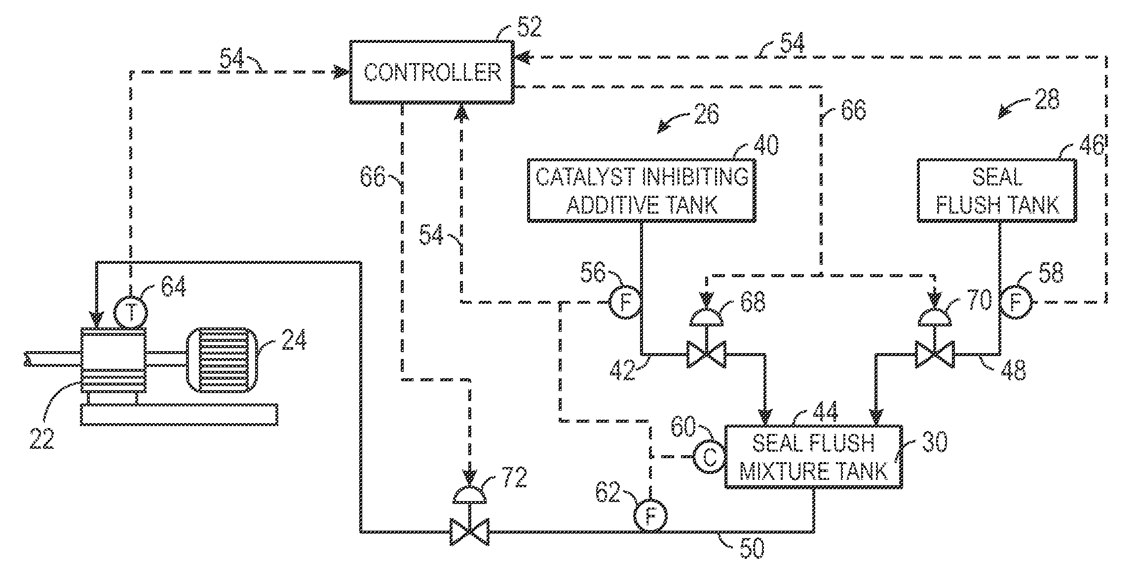
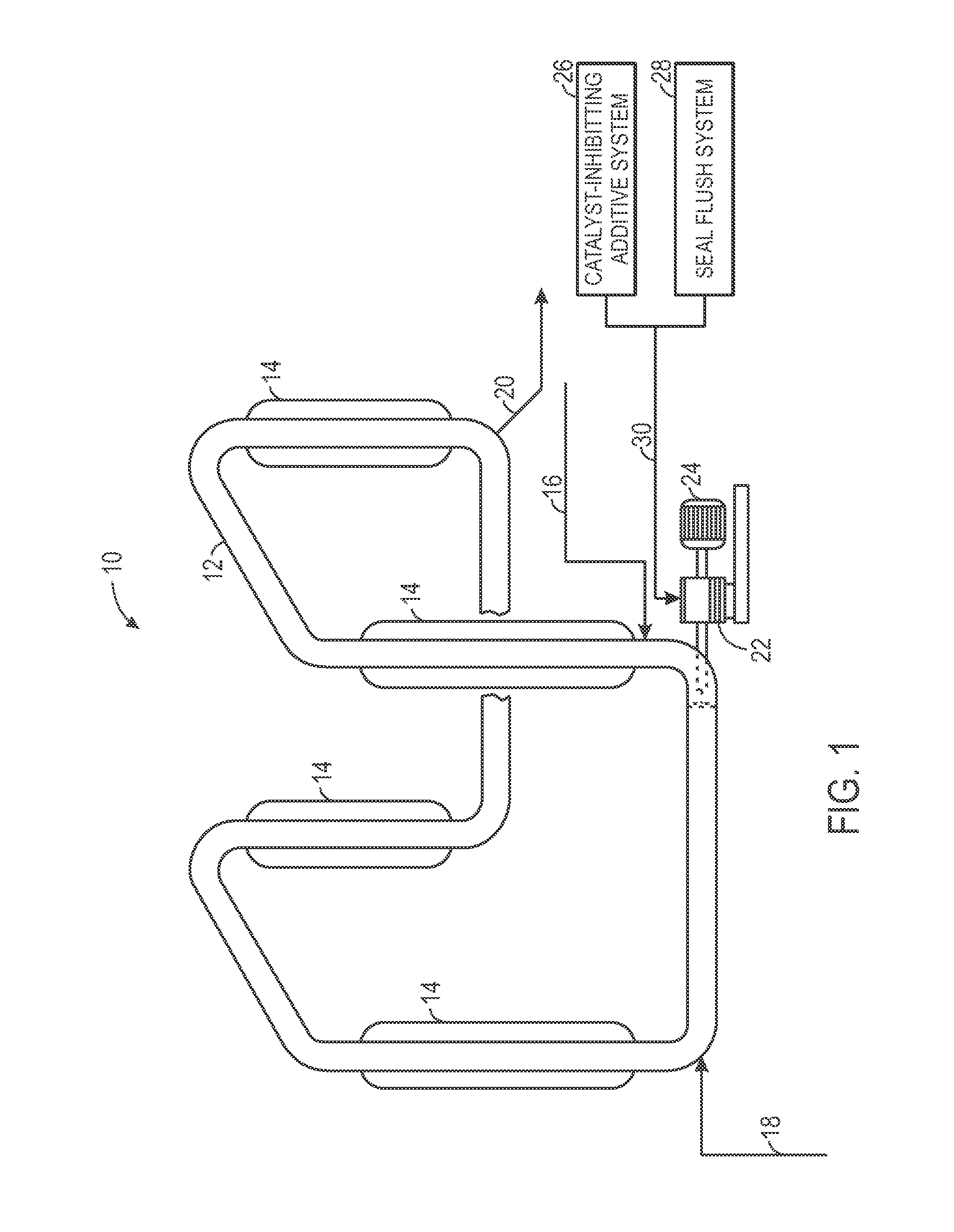
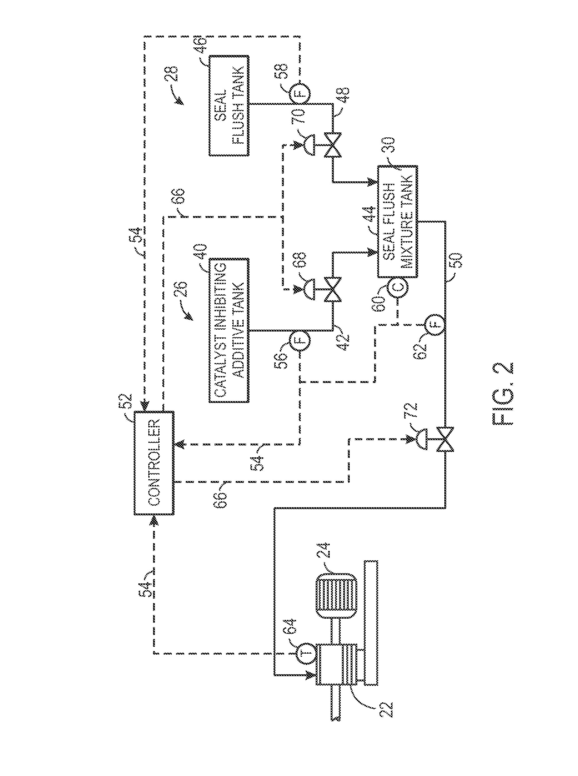
[0036] A system, comprising: a reactor circulation pump configured to circulate a slurry through a polymerization reactor, wherein the slurry comprises an olefin monomer, a catalyst, and a diluent; a catalyst-inhibiting additive system configured to supply a catalyst-inhibiting additive to a seal of the reactor circulation pump; and a seal flush system configured to generate a seal flush mixture and supply the seal flush mixture to the seal of the reactor circulation pump.

[0037]Embodiment 2. The system of embodiment 1, wherein the seal flush mixture comprises one or more catalyst-inhibiting additives selected from an antistatic agent, a catalyst poison, a catalyst inhibitor, an electron donor, a stereoregulator, a temper agent, a modifier, an adjuvant, a kill agent, an alcohol, water, a moderation system chemical, or any combination thereof.

embodiment 3

[0038] The system defined in any preceding embodiment, comprising one or more antistatic agents selected from a polysulfone, a polyamine, a sulfonic acid, toluene, or any combination thereof.

embodiment 4

[0039] The system defined in any preceding embodiment, wherein the seal flush mixture is configured to reduce a polymerization rate of the olefin monomer while in contact with the seal of the reactor circulation pump.


PUM


Abstract

Techniques are provided for seal flush systems. A system may include a reactor circulation pump configured to circulate a slurry through a polymerization reactor. The slurry may include an olefin monomer, a catalyst, and a diluent. The system may also include a catalyst-inhibiting additive system configured to supply a catalyst-inhibiting additive to a seal of the reactor circulation pump and a seal flush system configured to generate a seal flush mixture and supply the seal flush mixture to the seal of the reactor circulation pump.

Description

BACKGROUND[0001]The present disclosure relates generally to seal flush systems, and more particularly, to seal flush systems for polymerization reactor systems.[0002]This section is intended to introduce the reader to aspects of art that may be related to aspects of the present disclosure, which are described and / or claimed below. This discussion is believed to be helpful in providing the reader with background information to facilitate a better understanding of the various aspects of the present disclosure. Accordingly, it should be understood that these statements are to be read in this light and not as admissions of prior art.[0003]Polyolefins, such as polyethylene and polypropylene, may be prepared by particle form polymerization, also referred to as slurry polymerization. In this technique, feed materials, such as monomer, catalyst, slurry, and additives, are fed to a loop reactor to establish a slurry. In the loop reactor, the slurry is circulated while polymerization occurs, ...

Claims


Application Information

Patent Timeline
Patent Type & Authority Patents(United States)
IPC IPC(8): B01J19/00F04D29/10F04D29/12F04D29/70B01J19/18F04D7/04
CPCB01J19/0073B01J19/1837F04D7/04F04D29/106F04D29/126F04D29/708B01J2219/00006B01J2219/00247B01J2219/00252B01J2219/00256B01J2219/00272Y10T137/0318B01J19/2455B01J2219/24C08F2/01F04D3/005F04D7/00F04D13/06F04D29/043F04D29/181
Inventor NGUYEN, THANHHOTTOVY, JOHN D.
Owner CHEVRON PHILLIPS CHEMICAL CO LP
Learn More