Wiring substrate, droplet ejection head, printing apparatus, electronic device, and manufacturing method for wiring substrate

a manufacturing method and droplet technology, applied in the direction of printed circuit non-printed electric components association, sustainable manufacturing/processing, final product manufacturing, etc., can solve the problems of deteriorating shape accuracy, short circuit of wires, uneven surface of recessed section,

Active Publication Date: 2016-04-26
SEIKO EPSON CORP
View PDF6 Cites 1 Cited by
  • Summary
  • Abstract
  • Description
  • Claims
  • Application Information

AI Technical Summary

Benefits of technology

[0011]The length along the surface of the adhesive between the first wire and the second wire is referred to herein as an inter-wire length. As the inter-wire length increases, the potential for migration is reduced between the first wire and the second wire and the possibility of a short circuit between the wires is also reduced. The inter-wire length increased when the recessed section is present compared with when the recessed section is absent in the adhesive. Therefore, when the recessed section is present, it is possible to further suppress occurrence of migration and prevent a short circuit between the wires.Application Example 2
[0015]According to this application example, the depth of the recessed section is equal to or larger than 1 μm and equal to or smaller than 50 μm. When the depth of the recessed section is equal to or larger than 1 μm, an effect due to an increase in the inter-wire length is seen. Therefore, it is possible to prevent migration from easily occurring between the first wire and the second wire. When the depth of the recessed section exceeds 50 μm, shape accuracy is deteriorated because the influence of deformation of the adhesive during contraction becomes conspicuous. Therefore, by setting the depth of the recessed section to be equal to or larger than 1 μm and equal to or smaller than 50 μm, it is possible to prevent a short circuit between the wires and obtain the wiring substrate having high shape accuracy.Application Example 4
[0023]The length along the surface of the adhesive between the first wire and the second wire is referred to herein as an inter-wire length. As the inter-wire length is larger, migration less easily occurs between the first wire and the second wire and a short circuit between the wires less easily occurs. The inter-wire length can be large when the recessed section is present as compared with when the recessed section is absent in the adhesive. Therefore, when the recessed section is present, it is possible to further suppress occurrence of migration and prevent a short circuit between the wires. As a result, the droplet ejection head can suppress occurrence of migration and prevent a short circuit between the wires.Application Example 7
[0026]As the inter-wire length is larger, migration is less likely to occur between the first wire and the second wire and a short circuit between the wires is also less likely to occur. The inter-wire length can be set large when the recessed section is present compared with when the recessed section is absent. Therefore, when the recessed section is present, it is possible to further suppress the occurrence of migration and prevent short circuits between the wires. As a result, the printing apparatus is described which can suppress occurrence of migration and prevent a short circuit between the wires.Application Example 8

Problems solved by technology

Consequently, there is a risk that a short circuit may occur among the wires.
When the depth of the recessed section exceeds 50 μm, shape accuracy is deteriorated because the influence of deformation of the adhesive during contraction becomes conspicuous.
That is, unevenness is formed on the surface of the recessed section.
As the inter-wire length is larger, migration less easily occurs between the first wire and the second wire and a short circuit between the wires less easily occurs.

Method used


Image

  • Wiring substrate, droplet ejection head, printing apparatus, electronic device, and manufacturing method for wiring substrate
  • Wiring substrate, droplet ejection head, printing apparatus, electronic device, and manufacturing method for wiring substrate
  • Wiring substrate, droplet ejection head, printing apparatus, electronic device, and manufacturing method for wiring substrate

Examples


first embodiment

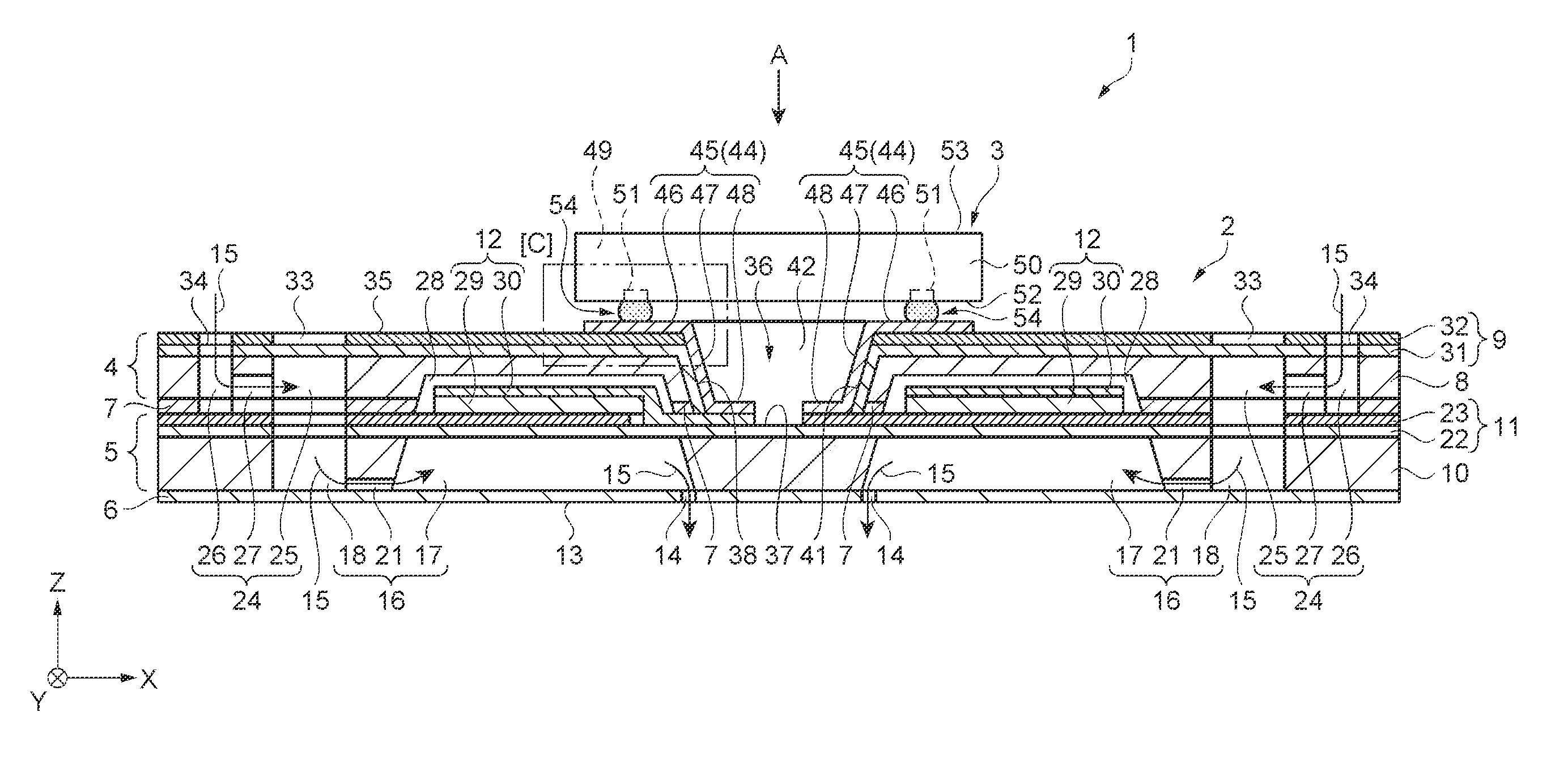
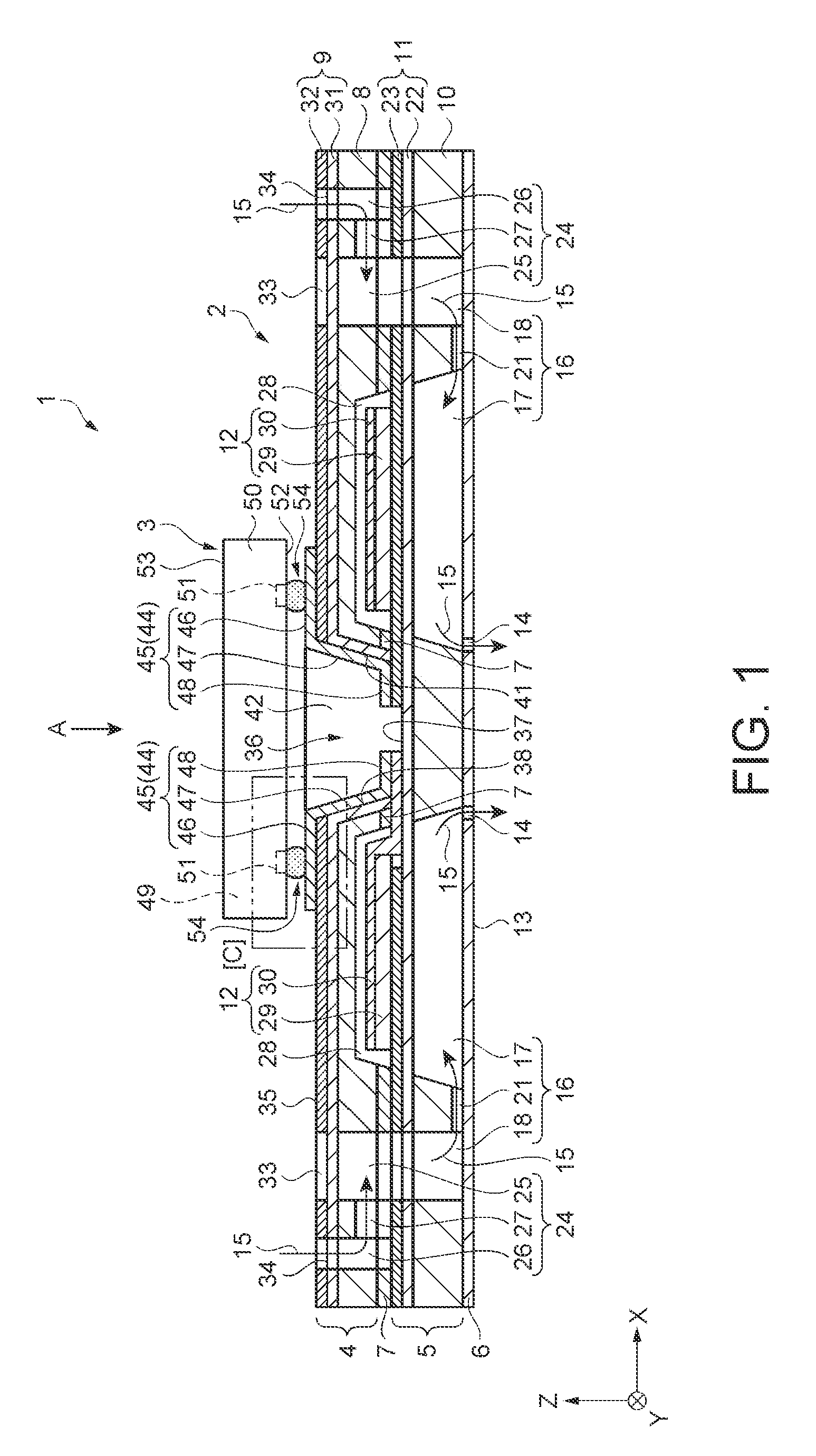
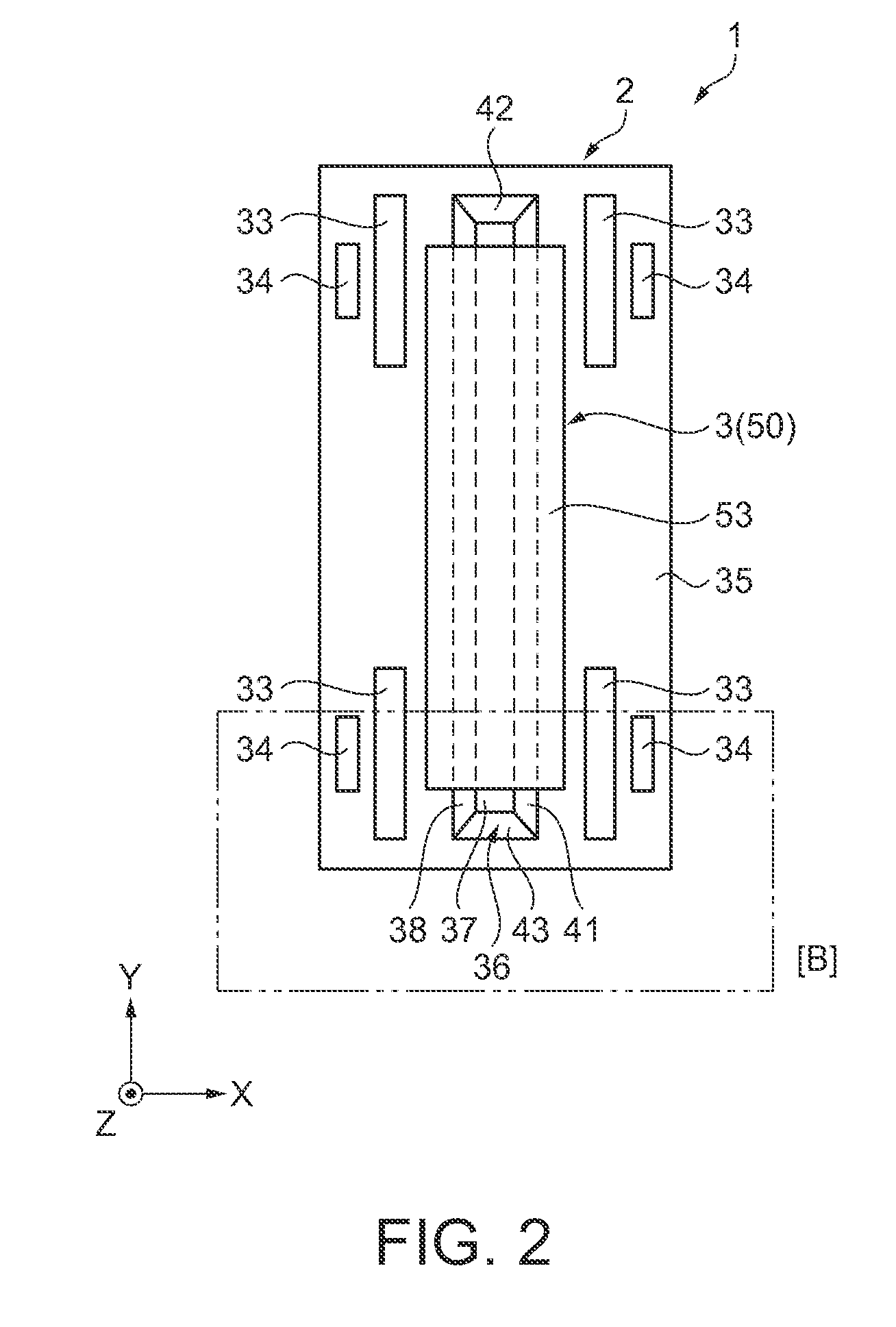
[0050]A droplet ejection head according to a first embodiment is explained with reference to FIGS. 1 to 6B. FIG. 1 is a schematic side sectional view showing the structure of the droplet ejection head. FIG. 2 is a schematic plan view showing the structure of the droplet ejection head and is a view of the droplet ejection head viewed from an arrow A direction in FIG. 1. FIG. 3 is a main part schematic plan view showing the structure of the droplet ejection head and is an enlarged detailed view of an area [B] surrounded by an alternate long and short dash line in FIG. 2.

[0051]As shown in FIGS. 1 and 2, a droplet ejection head 1 includes a base substrate 2 functioning as a tabular wiring substrate and an IC (Integrated Circuit) package 3 arranged on the base substrate 2. The droplet ejection head 1 is mounted on a printing apparatus (a droplet ejection apparatus). The droplet ejection head 1 can eject ink on a recording medium as droplets and perform printing on the recording medium.

[0...

second embodiment

[0104]A droplet ejection head according to a second embodiment is explained with reference to schematic diagrams of FIGS. 7A to 7C for explaining the structure of wires in a recessed section. FIG. 7A is a main part schematic side sectional view in the recessed section 36. FIG. 7B is a main part schematic side sectional view in an adhesive film. FIG. 7C is a main part schematic perspective view in the recessed section and is a diagram in which the sealing film 55 shown in FIGS. 4A and 4B are omitted. This embodiment is different from the first embodiment in that the films 56 shown in FIGS. 4A and 4B are omitted and the shape of the recessed section 57 is different. Note that explanation is omitted concerning similarities to the first embodiment.

[0105]In this embodiment, as shown in FIGS. 7A to 7C, a droplet ejection head 61 includes a base substrate 62. In the base substrate 62, the vibrating plate 11 and the reservoir forming substrate 8 are bonded by an adhesive film 63. In the adh...

third embodiment

[0111]A droplet ejection head according to a third embodiment is explained with reference to schematic diagrams of FIGS. 8A to 8C for explaining the structure of wires in a recessed section. FIG. 8A is a main part schematic side sectional view in the recessed section 36. FIG. 8B is a main part schematic side sectional view in the adhesive film. FIG. 8C is a main part schematic perspective view in the recessed section 36 and is a diagram in which the sealing film 55 is omitted. This embodiment is different from the first embodiment in that the shape of the recessed section 57 shown in FIGS. 4A to 4C is different. Note that explanation is omitted concerning similarities to the first embodiment.

[0112]In this embodiment, as shown in FIGS. 8A to 8C, a droplet ejection head 68 includes a base substrate 69. In the base substrate 69, the vibrating plate 11 and the reservoir forming substrate 8 are bonded by an adhesive film 70. A surface of the adhesive film 70 in contact with the wires 45 ...


PUM


Abstract

A wiring substrate includes a device substrate having a first surface, a sealing plate having a second surface superimposed on the first surface via an adhesive film and crossing the first surface, and wires set along the surfaces of the first surface, the adhesive film, and the second surface. The wiring substrate includes, between the wires adjacent to each other, a recessed section forming a recess with respect to a first bonding surface of the adhesive which is in contact with the first wire and a second bonding surface of the adhesive which is in contact with the second wire.

Description

RELATED APPLICATIONS[0001]The present invention claims priority to Japanese Patent Application No. 2014-001430, filed Jan. 8, 2014, which is incorporated herein by reference in its entirety.BACKGROUND[0002]1. Technical Field[0003]The present invention relates to a wiring substrate, droplet ejection head, printing apparatus, electronic device, and manufacturing method for the wiring substrate.[0004]2. Related Art[0005]Printing apparatuses are commonly used to eject droplets of liquid from an ejection head to perform a printing process on a recording medium, such as a printing sheet. One example of one such printing apparatus including the droplet ejection head is disclosed in JP-A-2006-289943 (Patent Literature 1). As is described in Patent Literature 1, the droplet ejection head includes a cavity that stores ink and a channel forming substrate including an ejection port that communicates with the cavity and ejects the ink in the cavity as droplets. A piezoelectric element is arrange...

Claims


Application Information

Patent Timeline
Patent Type & Authority Patents(United States)
IPC IPC(8): B41J2/04B41J2/14H05K1/02H05K3/02B41J2/16H05K1/18
CPCB41J2/14B41J2/14233B41J2/164H05K1/0284H05K1/0298H05K1/181H05K3/02B41J2002/14491H01L2224/16225H05K2201/09036H05K2201/10234H05K1/0306H05K3/4688H05K3/4697H05K2201/09072H05K2201/10446H05K2203/1173Y02P70/50
Inventor YOSHIIKE, MASASHI
Owner SEIKO EPSON CORP
Why Eureka
Try Eureka