Turbojet venting pipe, method for mounting one such pipe and turbojet provided with one such pipe
a technology for turbojets and venting pipes, which is applied in the direction of couplings, machines/engines, manufacturing tools, etc., can solve the problems of complex systems, mounting problems, and insufficient clearance, and achieve the effect of convenient manufacture and installation
- Summary
- Abstract
- Description
- Claims
- Application Information
AI Technical Summary
Benefits of technology
Problems solved by technology
Method used
Image
Examples
first embodiment
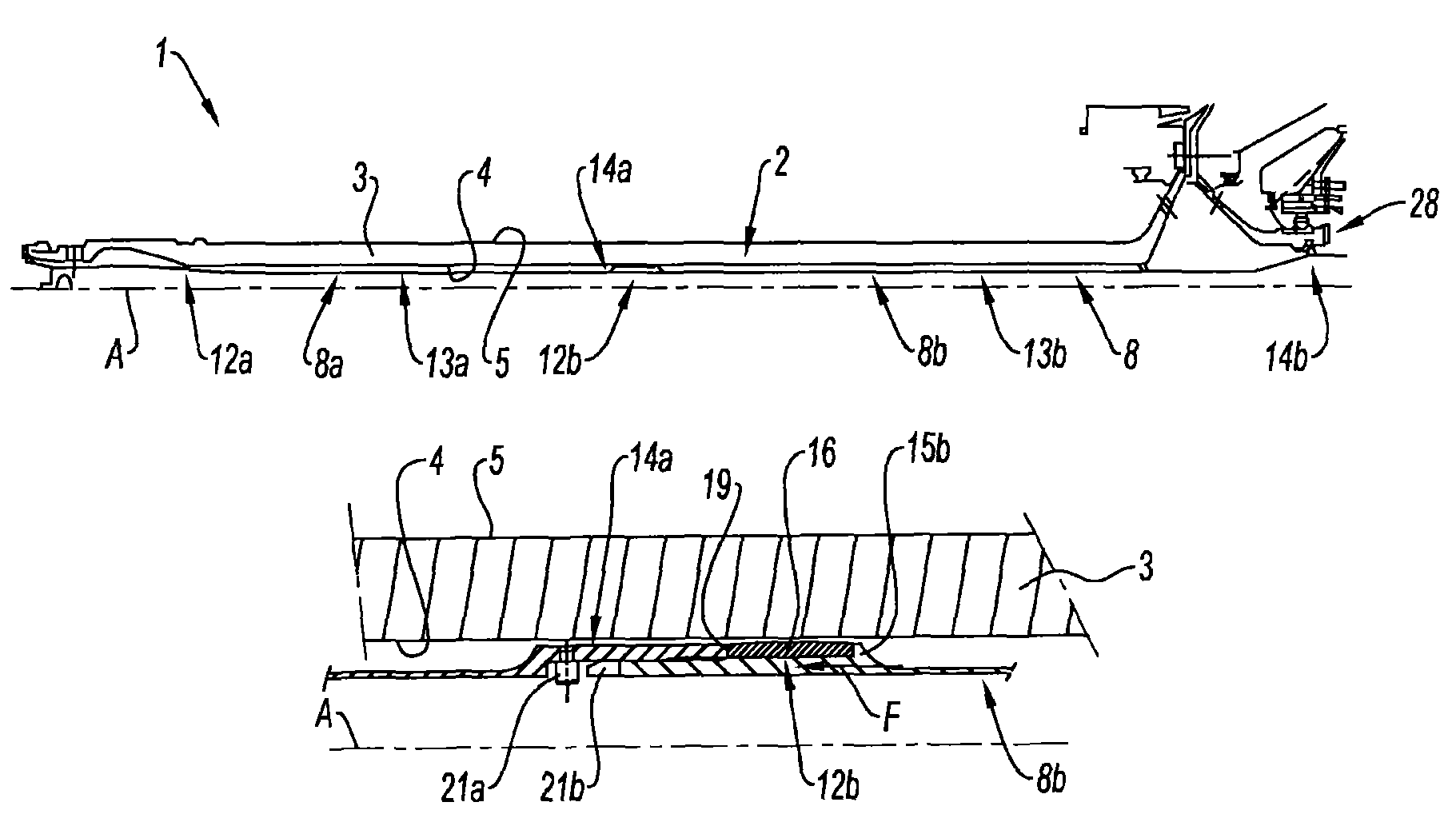
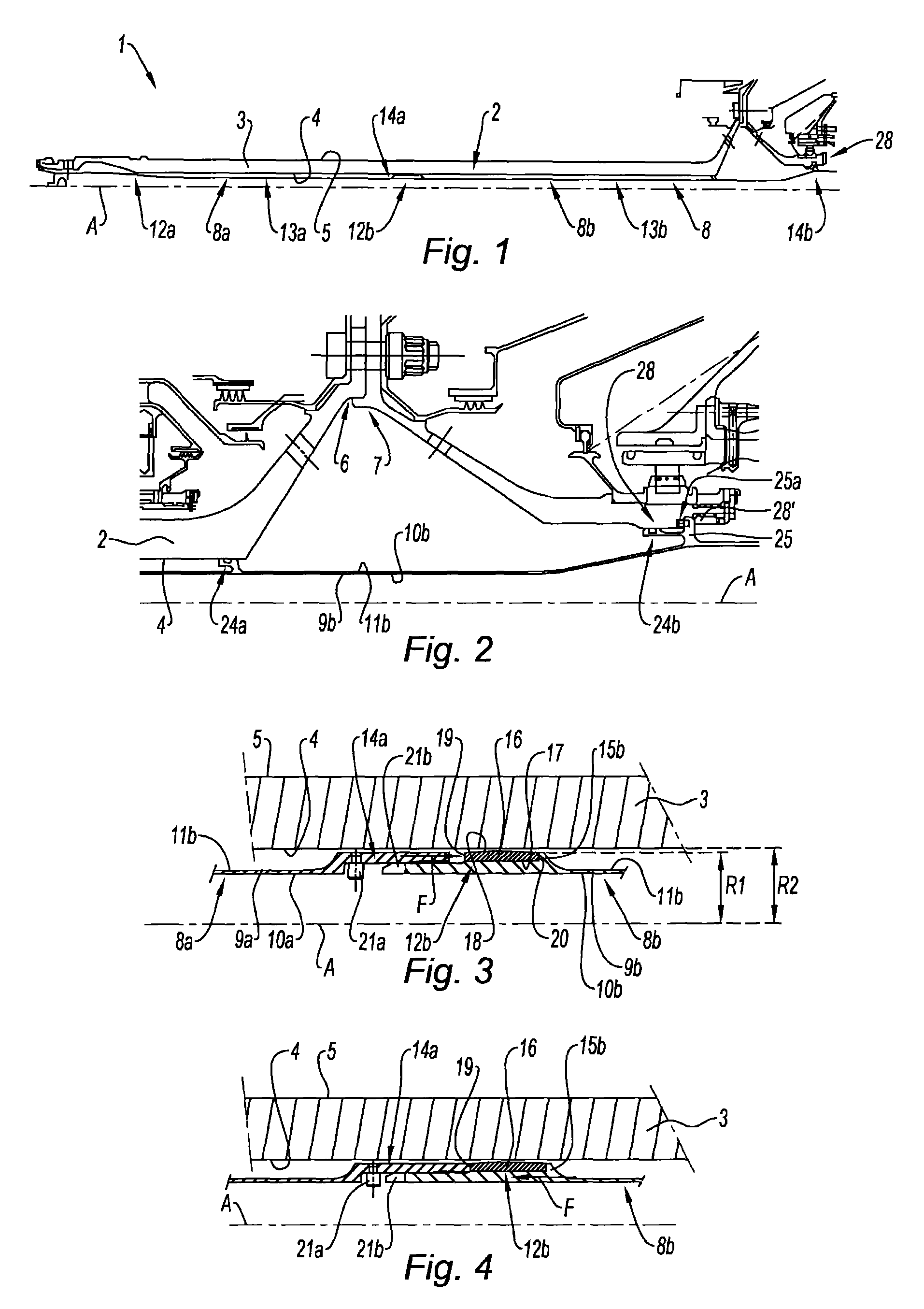
[0058]Referring to FIG. 11, a turbojet 1 according to the invention comprises, in the conventional way, a fan S, a low-pressure compressor 1a, a high-pressure compressor 1b, a combustion chamber 1c, a high-pressure turbine 1d, a low-pressure turbine 1e and an exhaust nozzle 1h. The high-pressure compressor 1b and the high-pressure turbine 1d are connected by a high-pressure shaft 1f and form therewith a high-pressure core. The low-pressure compressor 1a and the low-pressure turbine 1e are connected by a low-pressure shaft 2 and form therewith a low-pressure core. The turbojet 1 has, substantially at the upstream end of the high-pressure body, an “upstream compartment” E1 containing components of the rolling bearing and gearing type and, substantially at the downstream end of the high-pressure body, a “downstream compartment” E2 containing components of the rolling bearing type.
[0059]The low-pressure shaft 2 extends along an axis A which is the overall axis of the turbojet 1. In the ...
second embodiment
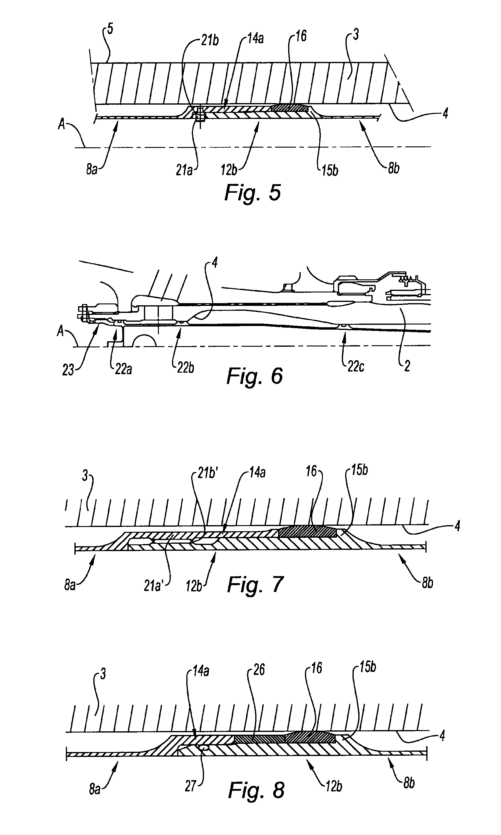
[0082]Referring to FIG. 7, the upstream segment 8a and the downstream segment 8b are secured in rotation by virtue of longitudinal splines 21a′, 21b′ respectively arranged on the downstream 14a and upstream 12b portions of these segments 8a, 8b. These splines 21a′, 21b′ are enmeshed in a manner known per se in order to secure the two segments 8a, 8b in rotation.
[0083]Of course, other means for securing the segments 8a, 8b in rotation and / or in translation with one another may be envisioned. For example, their downstream 14a and upstream 12b ends could be threaded and screwed to one another, in which case blocking in rotation is furthermore ensured.
third embodiment
[0084]Referring to FIG. 8, a rigid intermediate ring 26 is mounted between the deformable ring 16 and the downstream end 14a of the upstream segment 8a; such a rigid ring 26 makes it possible to hold the deformable ring 16 in position. It is, for example, adhesively bonded to the deformable ring 16 on their contact faces. The rigid ring 26 slides over the downstream segment 8b during the displacement of the upstream segment 8a and the compression of the deformable ring 16, the upstream segment 8a transmitting its compression forces to the ring 16 via the rigid ring 26.
[0085]Furthermore, in this embodiment, in proximity to the upstream end of its upstream end portion 12b, the downstream segment 8b comprises a sealing joint 27 housed in a groove and arranged in order to be compressed radially between the upstream segment 8a and the downstream segment 8b in order to avoid a possible gas leak in a possible clearance between these two segments 8a, 8b.
PUM
 Abstract
Description
Claims
Application Information
 - R&D
- Intellectual Property
- Life Sciences
- Materials
- Tech Scout
- Unparalleled Data Quality
- Higher Quality Content
- 60% Fewer Hallucinations
Browse by: Latest US Patents, China's latest patents, Technical Efficacy Thesaurus, Application Domain, Technology Topic, Popular Technical Reports.
© 2025 PatSnap. All rights reserved.Legal|Privacy policy|Modern Slavery Act Transparency Statement|Sitemap|About US| Contact US: help@patsnap.com


