Micro-valve and sealing device for use in a microfluidic system, and method for the production thereof

Active Publication Date: 2016-04-26
FRAUNHOFER GESELLSCHAFT ZUR FOERDERUNG DER ANGEWANDTEN FORSCHUNG EV
View PDF28 Cites 0 Cited by
  • Summary
  • Abstract
  • Description
  • Claims
  • Application Information

AI Technical Summary

Benefits of technology

The invention aims to improve the production of microvalves and sealing devices for disposable products. The technical effect of the invention is to provide a method that is economical and suitable for mass production of such products.

Problems solved by technology

Even though the rotor and the stator are loose parts in this case and seem suitable for onetime use, still a considerable expense is required to assembly the functional valve and thus the manipulation of the valve become more difficult.
The microvalve arrangement of FIG. 1 is of simple construction when compared to the aforesaid prior art, yet still a multitude of different materials and components are needed and the onetime assembly is still too elaborate in practice for a mass production.

Method used


Image

  • Micro-valve and sealing device for use in a microfluidic system, and method for the production thereof
  • Micro-valve and sealing device for use in a microfluidic system, and method for the production thereof
  • Micro-valve and sealing device for use in a microfluidic system, and method for the production thereof

Examples


Embodiment Construction

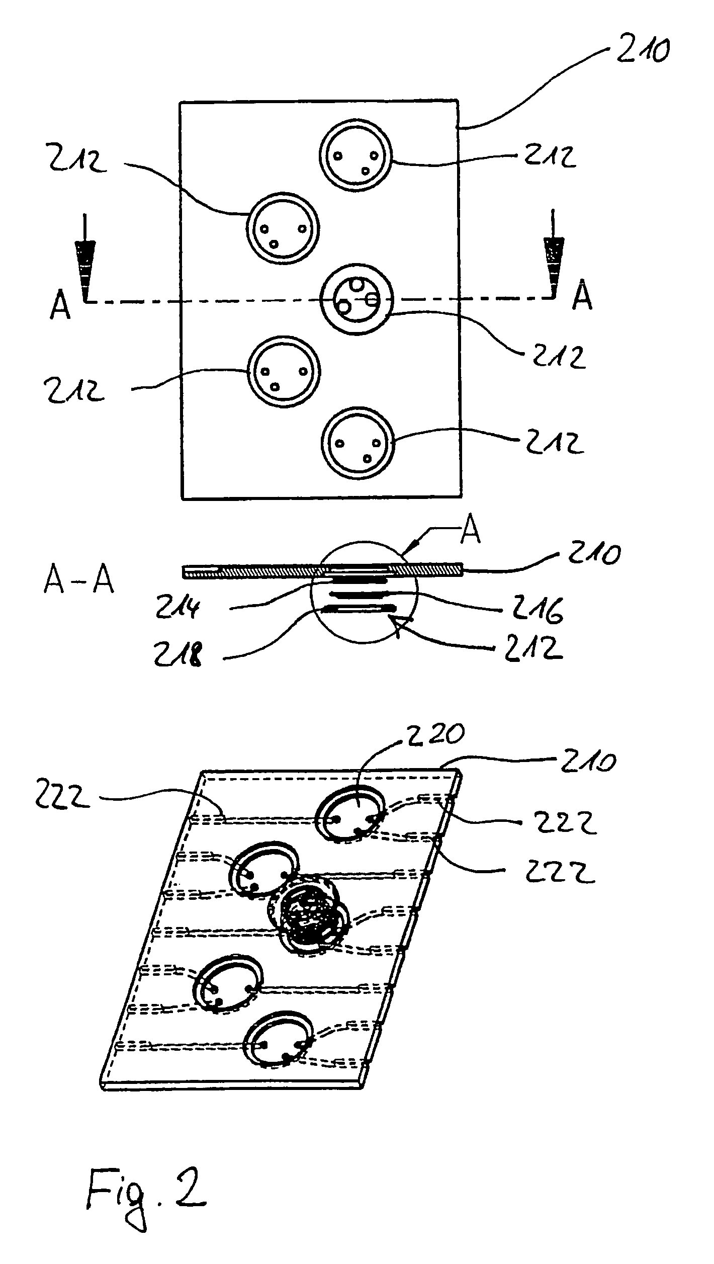
[0038]FIG. 2 shows a sample processing chip 210 according to the invention in three views, which at the same time constitutes the substrate for five microvalves 212 of the invented kind. The microvalves 212 are configured as rotary valves. In this embodiment, they have an elastomer seal 214 and a shape-stable part 216, which together form the valve body. The valve body is forced by means of a pressing ring 218 against a base and sealing surface 220 in the valve seat in the substrate 210. The valve seat is fashioned as a stepped cylindrical hollow in the substrate 210. The deeper step of the hollow forms the actual valve seat with the sealing surface 220. The shallower hollow with larger diameter forms the seat for the pressing ring 212, so that the entire installation consisting of valve body and pressing ring closes off the surface of the substrate 210 flush. At the bottom of FIG. 2 one notices that fluid lines 222 extend through the substrate 210, which empty into the valve seat i...


PUM

PropertyMeasurementUnit
Elasticityaaaaaaaaaa

Abstract

A micro-valve for controlling fluid flows and a sealing device for sealing off cavities in a microfluid system, in particular in a lab-on-a-chip system, and also a method for the production thereof. A valve body or a sealing element bears with a sealing surface against a sealing surface of a substrate, the valve body or the sealing element is pressed with the sealing surface thereof in a fluid-tight manner against the sealing surface of the substrate by means of a pressure-exerting ring, and the pressure-exerting ring is cohesively connected to the substrate. The pressure-exerting ring and / or the valve body or the sealing element are at least partially elastic.

Description

FIELD OF THE INVENTION[0001]The invention concerns a microvalve for control of fluid streams and a sealing device for the sealing of cavities in a microfluidics system, especially in a lab-on-a-chip system as well as a method for its production. The microvalve has a substrate with a sealing surface and a valve body disposed movably relative to the substrate, which has a sealing surface and defines at least one channel for optional connection and / or separation of fluid lines in the substrate, wherein the sealing surface of the valve body and the sealing surface of the substrate lie against each other in a fluid-tight manner. The sealing device has a substrate with a sealing surface and a sealing element, having a sealing surface for sealing off a cavity in the substrate. The invention further relates to a sample processing chip with such a microvalve and / or such a sealing device.[0002]A sample processing chip in the sense of this invention is a microfluidic system for chemical and bi...

Claims


Application Information

Patent Timeline
IPC IPC(8): F16K99/00B01L3/00
CPCB01L3/502738F16K99/0001F16K99/0013B01L2200/0689B01L2300/0816B01L2400/0622B01L2400/0644F16K2099/0084Y10T29/49412Y10T29/49425B29C65/08B29C65/16B29C66/1222B29C66/1224B29C66/24221B29C66/30223B29C66/472B29C66/5346B29C66/61B29C66/8322
Inventor SCHAEFFER, EVASTEIN, VOLKMAR
Owner FRAUNHOFER GESELLSCHAFT ZUR FOERDERUNG DER ANGEWANDTEN FORSCHUNG EV
Why Eureka
Try Eureka