Variable geometry aircraft wing supported by struts and/or trusses

a technology of oblique wings and supporting structures, applied in the direction of wings, wing adjustment, drag reduction, etc., can solve the problems of insufficient strength or stability of conventional oblique wings, poor performance of wings, and inability to resist transverse bending. to achieve the effect of improving aerodynamic performance, reducing airport runway length requirements, and increasing strength and stability

Active Publication Date: 2016-05-03
NASA
View PDF7 Cites 17 Cited by
  • Summary
  • Abstract
  • Description
  • Claims
  • Application Information

AI Technical Summary

Benefits of technology

[0007]Certain embodiments of the present invention may be implemented and provide solutions to the problems and needs in the art that have not yet been fully solved by conventional oblique aircraft wings. For example, in some embodiments, an oblique variable-sweep wing is braced by struts and/or trusses in order to increase strength and stability. Such embodiments may (1) improve aerodynamic performance during low speed flight shortly after takeoff without a

Problems solved by technology

For instance, it is generally preferable to have a wing with little or no sweep at takeoff speeds, but such a wing performs poorly as speed increases towards sup

Method used


Image

  • Variable geometry aircraft wing supported by struts and/or trusses
  • Variable geometry aircraft wing supported by struts and/or trusses
  • Variable geometry aircraft wing supported by struts and/or trusses

Examples


Embodiment Construction

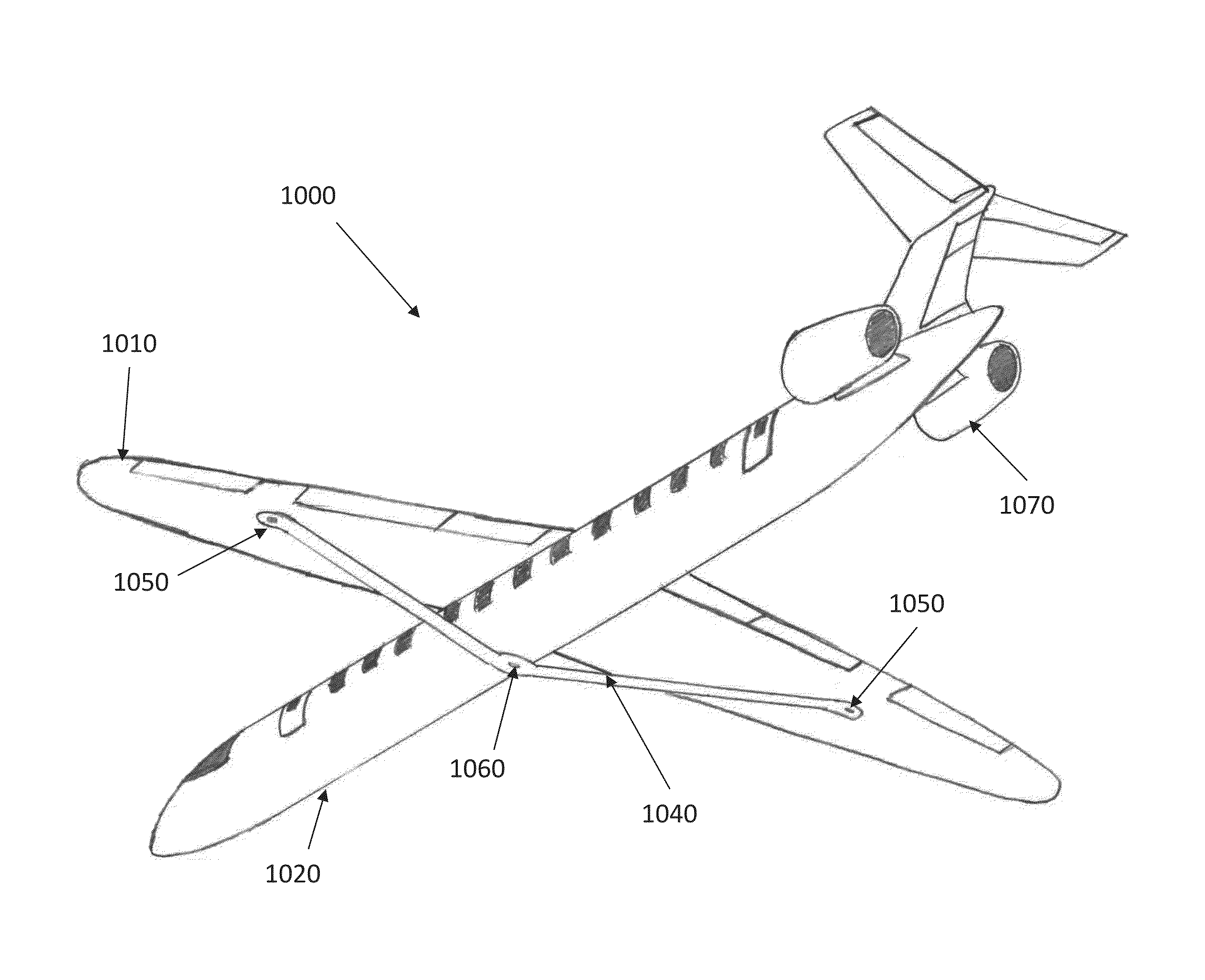
[0037]Some embodiments of the present invention pertain to a strut and / or truss braced configuration for an oblique wing. In some embodiments, the brace (strut and / or truss) is a load carrying structure that is either a single element strut or a more complex multi-element truss. As used herein, the term “brace” is an all-inclusive term that covers all suitable forms of load transmitting structures, of which struts and trusses are examples. In certain embodiments, an aircraft utilizes a strut and / or truss-braced, continuous span wing, where the wing is attached to the fuselage with a mechanical pivot, and the sweep of the wing may be adjusted in-flight to maximize aircraft performance and efficiency on adjusted on the ground to minimize aircraft spotting factor.

[0038]In some embodiments, the only essential differential motion that occurs is between the wing and fuselage. In some such embodiments, the wing, braces, and any wing mounted engines may move together as a single unit with n...


PUM


Abstract

The present invention provides an aircraft having variable airframe geometry for accommodating efficient flight. The aircraft includes an elongated fuselage, an oblique wing pivotally connected with said fuselage, a wing pivoting mechanism connected with said oblique wing and said fuselage, and a brace operably connected between said oblique wing and said fuselage. The present invention also provides an aircraft having an elongated fuselage, an oblique wing pivotally connected with said fuselage, a wing pivoting mechanism connected with said oblique wing and said fuselage, a propulsion system pivotally connected with said oblique wing, and a brace operably connected between said propulsion system and said fuselage.

Description

CROSS REFERENCE TO RELATED APPLICATION[0001]This application is a non-provisional of, and claims priority to, U.S. Provisional Patent Application Ser. No. 61 / 764,797 filed Feb. 14, 2013. The subject matter of the provisional application is hereby incorporated by reference in its entirety.ORIGIN OF THE INVENTION[0002]The invention described herein was made by (an) employee(s) of the United States Government and may be manufactured and used by or for the Government of the United States of America for governmental purposes without the payment of any royalties thereon or therefor.FIELD OF THE INVENTION[0003]The present invention generally pertains to aircraft wing configurations, and more specifically, to support structures for a rotatable oblique aircraft wing.BACKGROUND[0004]The optimal wing sweep for flight of an aircraft varies based on speed. For instance, it is generally preferable to have a wing with little or no sweep at takeoff speeds, but such a wing performs poorly as speed i...

Claims


Application Information

Patent Timeline
IPC IPC(8): B64C3/38
CPCB64C3/385B64C3/40Y02T50/10
Inventor MELTON, JOHN E.DUDLEY, MICHAEL R.
Owner NASA
Why Eureka
Try Eureka