Refrigerant circuit of an air conditioner with heat pump

a technology of refrigerant circuit and air conditioner, which is applied in the direction of domestic cooling apparatus, lighting and heating apparatus, and cooling fluid circulation, etc., can solve the problems of not meeting the required level, heat pump systems that cannot dehumidify and heat the air supplied to the passenger compartment at the same time, and cannot be operated at low ambient temperatures with surrounding air, etc., to achieve adequate dehumidification of the intake air for the passenger compartment, sufficient heating power, and reduced power

Active Publication Date: 2016-05-24
HANON SYST
View PDF18 Cites 2 Cited by
  • Summary
  • Abstract
  • Description
  • Claims
  • Application Information

AI Technical Summary

Benefits of technology

[0032]The special advantage of the invention is that, when operating in the reheat mode, the pressure of the refrigerant in the reheater is set significantly above the pressure level in the condenser / gas cooler as the heat exchanger for the heat transfer between refrigerant and surroundings and thus the intake air for the passenger compartment can be heated substantially above the temperature of the ambient air. With the refrigerant circuit, sufficient heating power can be provided in the reheat mode both at high and at low ambient air temperature, for example, below 20° C. Furthermore, an adequate dehumidification of the intake air for the passenger compartment can be assured in this operating mode.
[0033]Further benefits of the refrigerant circuit of the air conditioning system as compared to the prior art can be summarized as follows: quick providing of warm air at low ambient temperatures and cold cooling water of the engine cooling circuit when used in hybrid vehicles, reduction of the required power for heating the passenger compartment and possible heating in recirculating ventilation operation, good dynamics and modest complexity as compared to other extra heating systems with comparable functionalities, and, reheat operation in which the heating power of the reheater is lower than the cooling power in the evaporator.

Problems solved by technology

The known systems with refrigerant / air heat exchangers, which draw heating power from the cooling circuit of an efficient internal combustion engine of the vehicle propulsion system at low ambient temperatures no longer achieve the required level for a comfortable heating of the passenger compartment to meet the overall heating demand of the passenger compartment.
Heat pump systems, which cannot dehumidify and heat the air supplied to the passenger compartment at the same time, cannot be operated at low ambient temperatures with surrounding air, that is, with air recirculating from the passenger compartment.
Due to the lack of a dehumidifying function, the remaining humidity of the air as well as the water given off in the form of vapor from the passengers would result in fogging of the windows.
But due to the low ambient temperature, the cooled and dehumidified air cannot be supplied directly to the passenger compartment.
In this case, when operating in the reheat mode the pressure of the refrigerant in the heat pump condenser cannot be adjusted significantly above the pressure level in the external heat exchanger and the intake air for the passenger compartment cannot be heated substantially above the temperature of the ambient air.
Consequently, at high ambient air temperatures, the system can adequately provide heating power when operating in the reheat mode, but it has a heating power deficit at low ambient air temperatures, for example, at temperatures below 20° C. In order to generate the required heating power, the system must be operated in the pure heat pump mode.
Yet in this operating mode, adequate dehumidification of the intake air for the passenger compartment cannot be realized.
However, in this design of the refrigerant circuit as well, the pressure of the refrigerant in the heat pump condenser cannot be adjusted independently of the ambient temperature and thus cannot be set significantly above the pressure level in the condenser of the primary circuit.
Although adequate heating power can be made available when operating in the reheat mode, the temperature level is not sufficient for a comfortable air conditioning of the passenger compartment at ambient air temperatures less than 20° C. To achieve the heating power needed for this, the air conditioning system has to be operated in the pure heat pump mode, but then sufficient dehumidification of the intake air for the passenger compartment cannot be assured.

Method used


Image

  • Refrigerant circuit of an air conditioner with heat pump
  • Refrigerant circuit of an air conditioner with heat pump

Examples


Embodiment Construction

[0037]The following detailed description and appended drawings describe and illustrate various exemplary embodiments of the invention. The description and drawings serve to enable one skilled in the art to make and use the invention, and are not intended to limit the scope of the invention in any manner. In respect of the methods disclosed, the steps presented are exemplary in nature, and thus, the order of the steps is not necessary or critical.

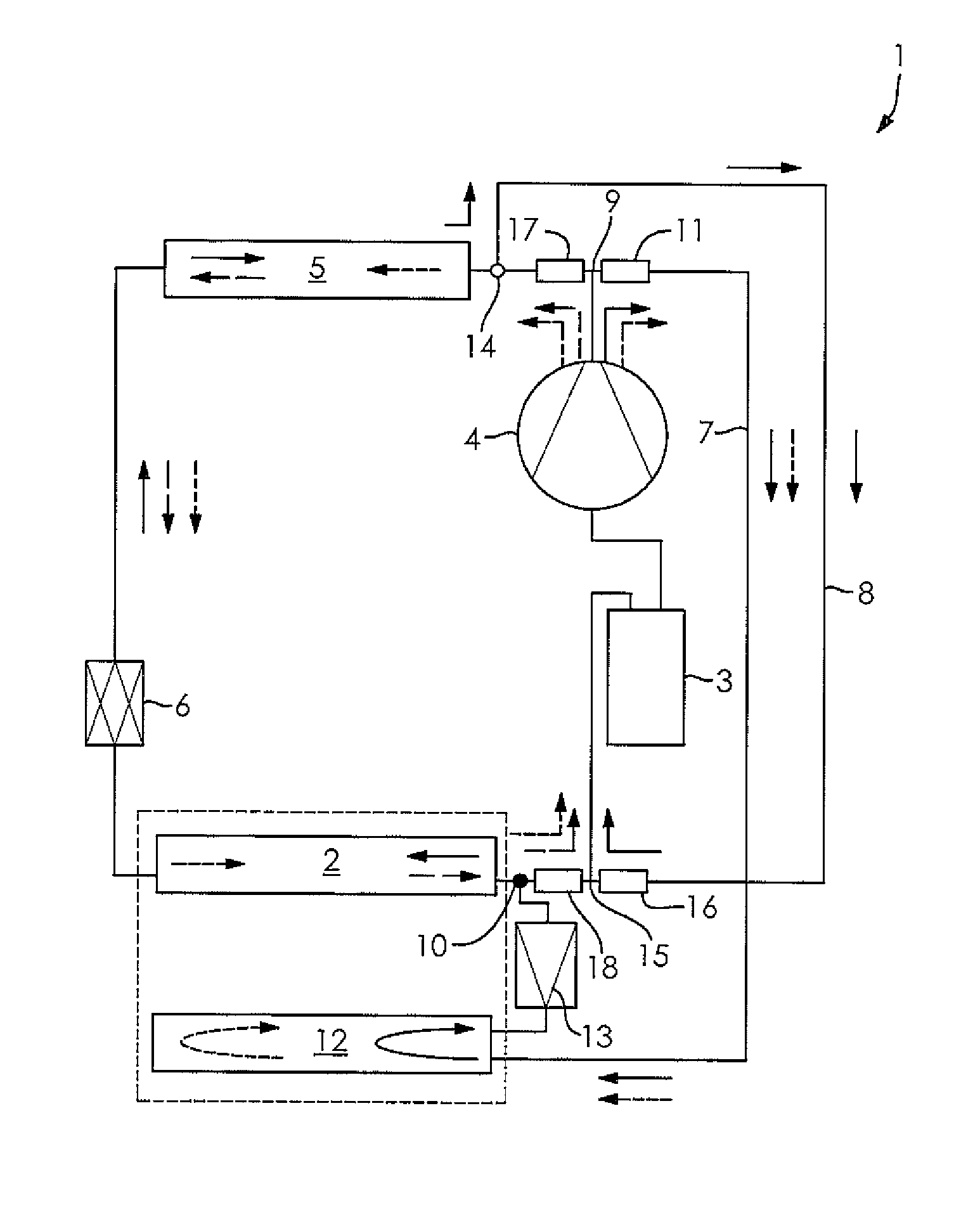
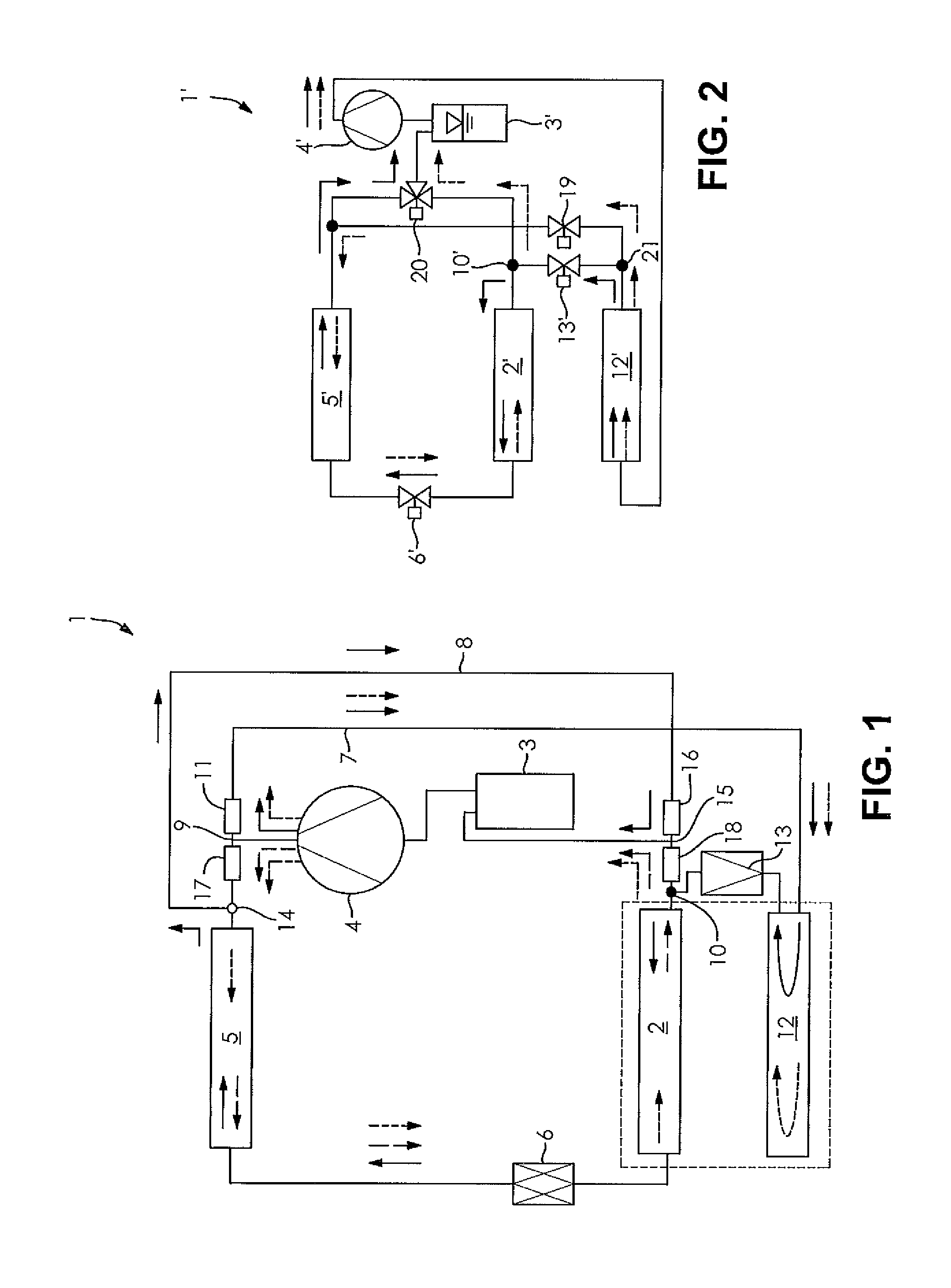
[0038]FIG. 1 shows a refrigerant circuit 1 of the vehicle's air conditioning system with a primary circuit and a secondary line or circuit. During operation in the cooling unit mode, the refrigerant flows through the primary circuit in succession through the heat exchanger 2, operated as an evaporator, the collector 3, the compressor 4, the heat exchanger 5 operated as a condenser / gas cooler, and the expansion element 6 configured as an expansion valve with bidirectional flow. The direction of flow of the refrigerant is shown here by means o...


PUM


Abstract

A refrigerant circuit of an air conditioning system for a passenger compartment of a motor vehicle having a primary circuit having a compressor configured to compress a refrigerant, a first heat exchanger in fluid communication with the compressor and configured to transfer heat between a refrigerant and the environment, a first expansion element in fluid communication with the first heat exchanger, and a second heat exchanger in fluid communication with the first expansion element and the compressor, the second heat exchanger configured to dehumidify intake air of the passenger compartment and a secondary circuit having a first flow pathway and a second flow pathway, the first flow pathway having a third heat exchanger in fluid communication with the compressor and configured to transfer heat from the refrigerant to the passenger compartment and a second expansion element in fluid communication with the third heat exchanger, and a third expansion element.

Description

CROSS-REFERENCE TO RELATED APPLICATION[0001]This application claims priority to German Provisional Patent Application Serial No. DE 10 2012 103 675.6 filed Apr. 26, 2012 and German Non-Provisional Patent Application Serial No. DE 10 2012 111 672.5 filed on Nov. 30, 2012, hereby incorporated herein by reference in its entirety.FIELD OF THE INVENTION[0002]The invention relates to a refrigerant circuit of an air conditioner for conditioning the air of a passenger compartment of a motor vehicle. The refrigerant circuit, designed for a combined operation in air conditioner and heat pump mode, has a compressor, a heat exchanger for heat transfer between the refrigerant and the surroundings, a first expansion element and a heat exchanger for heat transfer from the air of the passenger compartment being conditioned to the refrigerant and a heat exchanger for heat transfer from the refrigerant to the air of the passenger compartment being conditioned. Furthermore, the invention concerns a me...

Claims


Application Information

Patent Timeline
Patent Type & Authority Patents(United States)
IPC IPC(8): F25B1/00F25B13/00B60H1/32F25D17/06F25B27/00B60H1/00B60G1/02
CPCB60H1/00007B60H1/00899B60H1/3213B60G1/02B60H2001/00942B60H2001/3285B60H1/00921B60H1/00B60H1/18B60H1/32
Inventor GRAAF, MARCHAAS, TOBIAS
Owner HANON SYST
Why Eureka
Try Eureka