Method for forming dielectric thin film

a technology of dielectric thin film and dielectric core, which is applied in the direction of zirconium compounds, lead oxides, lead monoxide, etc., can solve the problem of difficult formation of pzt thin film having a (100)/(001) orientation

Active Publication Date: 2016-05-24
ULVAC INC
View PDF18 Cites 2 Cited by
  • Summary
  • Abstract
  • Description
  • Claims
  • Application Information

AI Technical Summary

Benefits of technology

[0021]The PZT thin film having a (100) / (001) orientation can be formed on a Pt or Ir thin film having a (111) orientation. The present invention provides a piezoelectric element having a piezoelectric characteristic larger than the conventional configuration.

Problems solved by technology

In other words, in the conventional method for forming the dielectric thin film, there has been a problem in that it is difficult to form a PZT thin film having a (100) / (001) orientation; see, for example, JPA No. 2007-327106, JPA No. 2010-084180 and JPA No. 2003-081694.

Method used


Image

  • Method for forming dielectric thin film
  • Method for forming dielectric thin film
  • Method for forming dielectric thin film

Examples


Embodiment Construction

[0028]A description will be given of a structure of a dielectric film forming apparatus used in a method for forming a dielectric thin film according to the present invention.

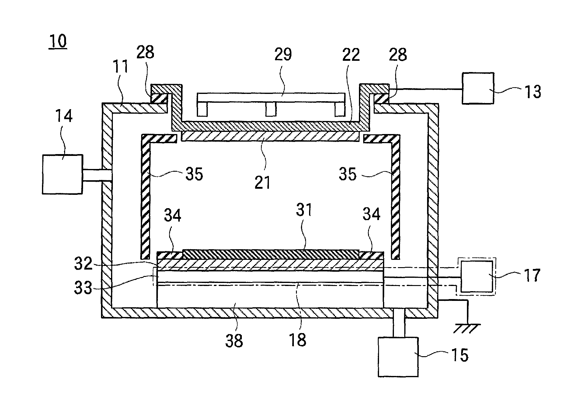
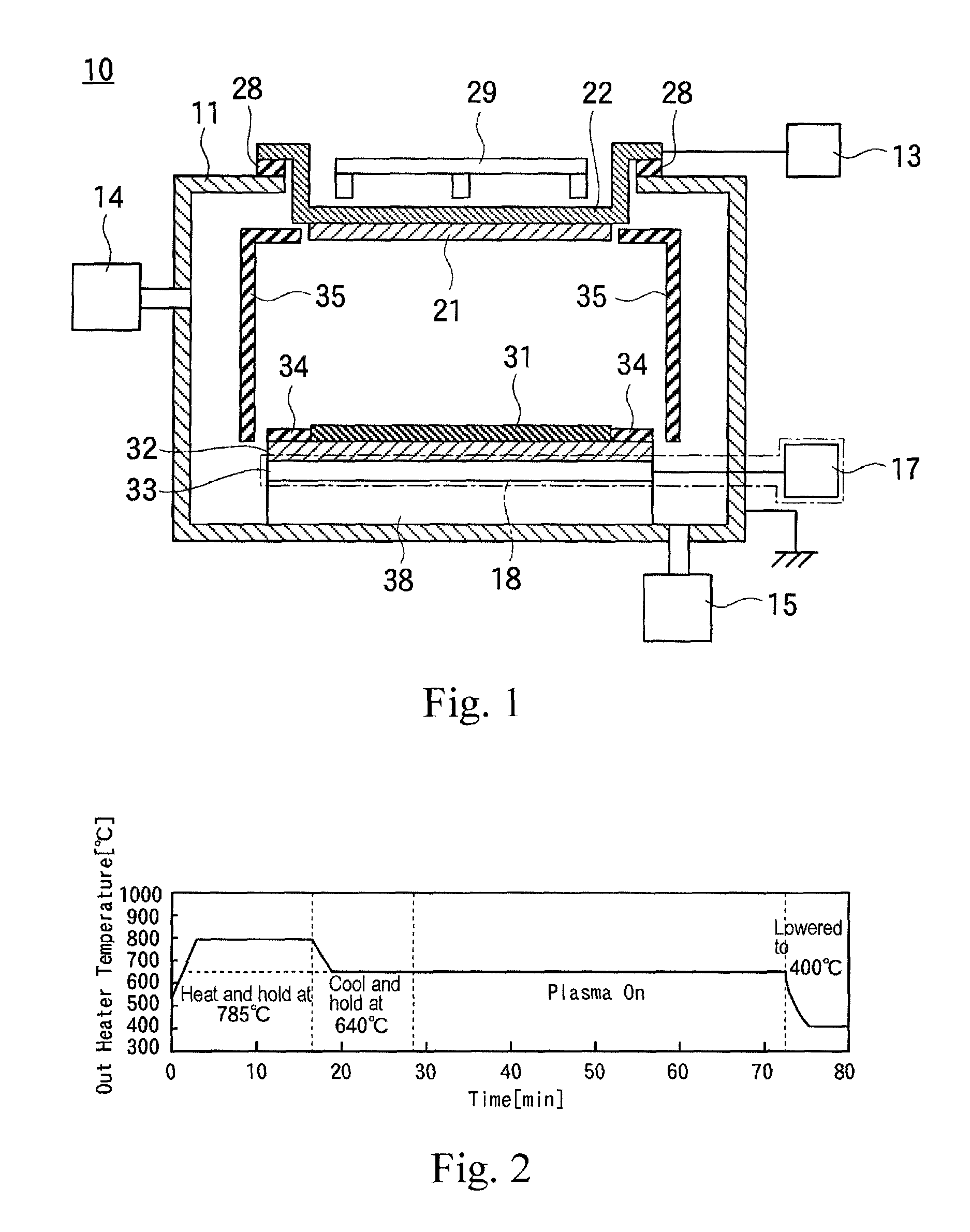
[0029]FIG. 1 is an internal configuration diagram of a dielectric film forming apparatus 10.

[0030]The dielectric film forming apparatus 10 includes a vacuum chamber 11, a target 21 of PZT provided in the vacuum chamber 11, a substrate holding pedestal 32 for holding a substrate 31 provided on a position facing the target 21, a substrate heating portion 18 for heating the substrate 31 held on the substrate holding pedestal 32, a sputtering power supply 13 applying electric voltage to the target 21, a sputtering gas introduction unit 14 for introducing a sputtering gas inside the vacuum chamber 11, and first and second deposition preventive plates 34 and 35 provided in the vacuum chamber at positions where PZT particles discharged from the target 21 adhere to.

[0031]A cathode electrode 22 is mounted on a wall surf...


PUM

PropertyMeasurementUnit
temperatureaaaaaaaaaa

Abstract

A method for forming a dielectric thin film that forms a PZT thin film having a (100) / (001) orientation. After a seed layer is formed by adhering PbO gas to a surface of a substrate, a voltage is applied to a target of lead zirconate titanate (PZT) and perform sputtering, while the substrate is heated inside of an evacuated vacuum chamber. Then, a PZT thin film is formed on the surface of the substrate. Because Pb and O are supplied from the seed layer, a PZT film having a (001) / (100) orientation can be formed without lack of Pb.

Description

BACKGROUND[0001]The present invention generally relates to a method for forming a dielectric thin film.[0002]Currently, a piezoelectric element using a ferroelectric material (such as, lead zirconate titanate (Pb (Zr, Ti)O3, PZT)) is applied to MEMS (micro electromechanical systems) technique (such as, an inkjet head and an acceleration sensor).[0003]FIG. 4 is a graph showing piezoelectric characteristics of a PZT thin film having a (100) / (001) orientation and a PZT thin film having a (111) orientation. The PZT thin film with (100) / (001) orientation is known to show a piezoelectric characteristic greater than the piezoelectric characteristic of the PZT thin film with the (111) orientation.[0004]A description will be given of a conventional method for forming a dielectric thin film.[0005]When a piezoelectric element is formed, as the substrate to be film formed, a Si substrate having a thermally-oxidized film on which a Ti thin film as an adhesive layer and a noble metal thin film as...

Claims


Application Information

Patent Timeline
Patent Type & Authority Patents(United States)
IPC IPC(8): H01L41/316C23C14/35H01J37/34C23C14/08C01G21/06C01G25/00C23C14/02
CPCC23C14/088C23C14/024C23C14/35H01J37/34H01J37/3426H01J37/3464H01L41/316C01G21/06C01G25/006C01P2002/72C01P2006/40H01L21/205H10N30/076
Inventor KIMURA, ISAOJINBO, TAKEHITOKOBAYASHI, HIROKIENDOU, YOUHEIOONISHI, YOUHEI
Owner ULVAC INC
Why Eureka
Try Eureka