Heat dissipating device

a heat dissipating device and heat dissipation technology, applied in the direction of basic electric elements, semiconductor devices, tubular elements, etc., can solve the problems of significant performance issues, electrical components may get damaged due to the accumulated heat, and the current in the circuit will generate unnecessary heat, etc., to achieve great thermal conductivity, enhance heat dissipation efficiency effectively, and great thermal conductivity

Active Publication Date: 2016-05-24
COOLER MASTER DEVELOPMENT CORP
View PDF24 Cites 2 Cited by
  • Summary
  • Abstract
  • Description
  • Claims
  • Application Information

AI Technical Summary

Benefits of technology

[0005]The invention provides a heat dissipating device capable of enhancing heat dissipating efficiency effectively.
[0007]As mentioned in the above, after forming the heat dissipating device, the heat absorbing segment of the heat pipe directly contacts the third base with great thermal conductivity and a surface of the third base is exposed. Accordingly, the exposed surface of the third base of the heat dissipating device can be attached to an electronic component, such that heat generated by the electronic component can be conducted to the heat absorbing segment of the heat pipe directly through the third base, so as to enhance heat dissipating efficiency effectively. Furthermore, the invention uses copper with great thermal conductivity to form the third base and uses aluminum with small thermal conductivity to form the second base and the fourth base. Since the fourth base only covers the periphery of the second base and does not contact the third base, the second base can prevent copper from melting and being mixed with the melted aluminum during the die casting process, so as to avoid increasing copper in the melted aluminum during the die casting process. Therefore, when the heat dissipating device of the invention is installed outside, the fourth base will not crack due to corrosion since the fourth base is formed by the die casting process. Consequently, the lifetime of the heat dissipating device of the invention can be extended effectively. Moreover, since the connecting segment of the heat pipe is covered by the sleeve, it not only can enhance the connecting strength between the heat pipe and the fourth base but also can prevent the heat pipe from cracking during the die casting process.

Problems solved by technology

When an electronic product is operating, the current in circuit will generate unnecessary heat due to impedance.
If the heat is accumulated in the electronic components of the electronic product without dissipating immediately, the electronic components may get damage due to the accumulated heat.
Therefore, the performance of heat dissipating device is a significant issue for the electronic product.
How to enhance heat dissipating efficiency of the heat dissipating device effectively has become a significant design issue.

Method used


Image

  • Heat dissipating device
  • Heat dissipating device
  • Heat dissipating device

Examples


first embodiment

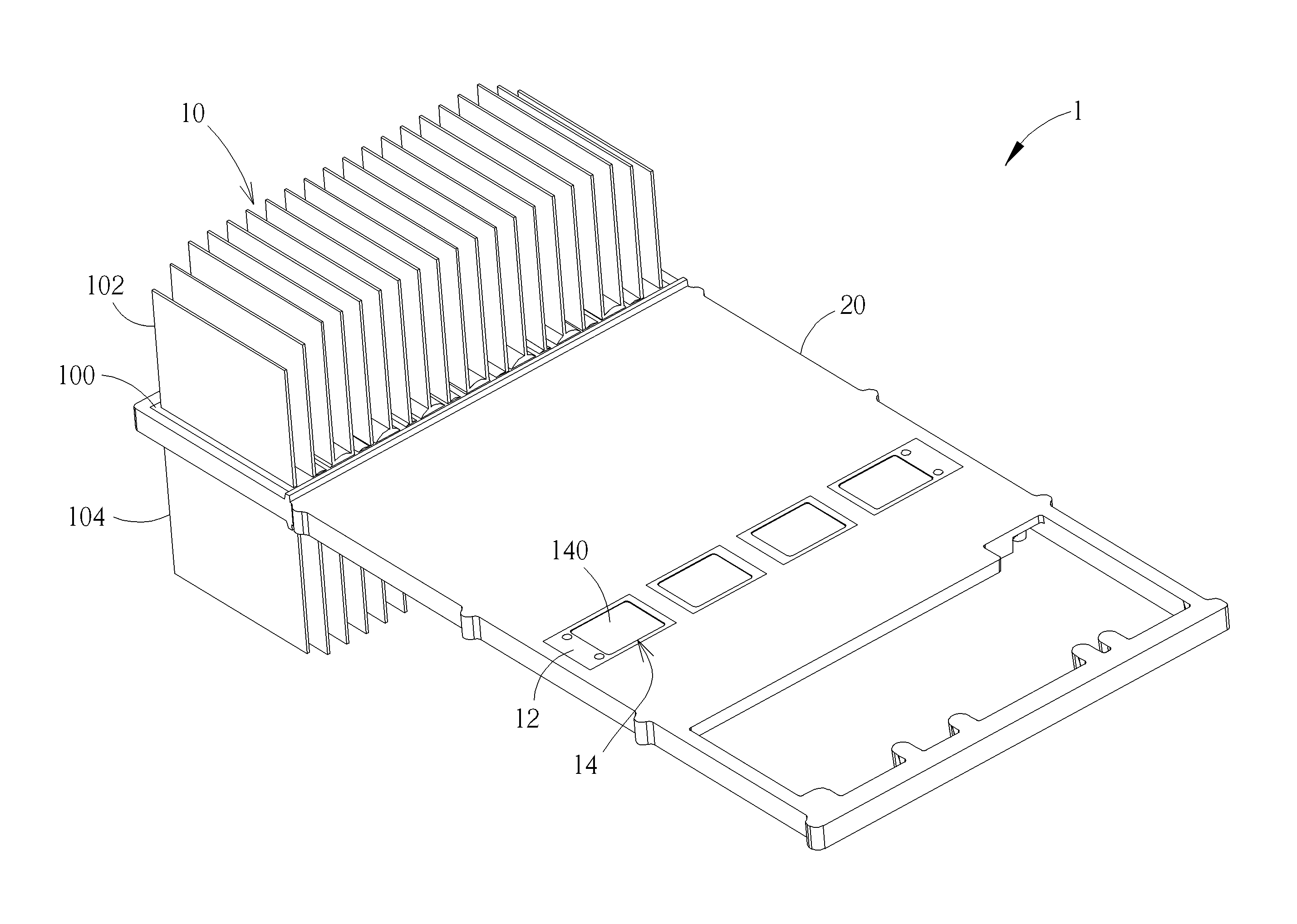
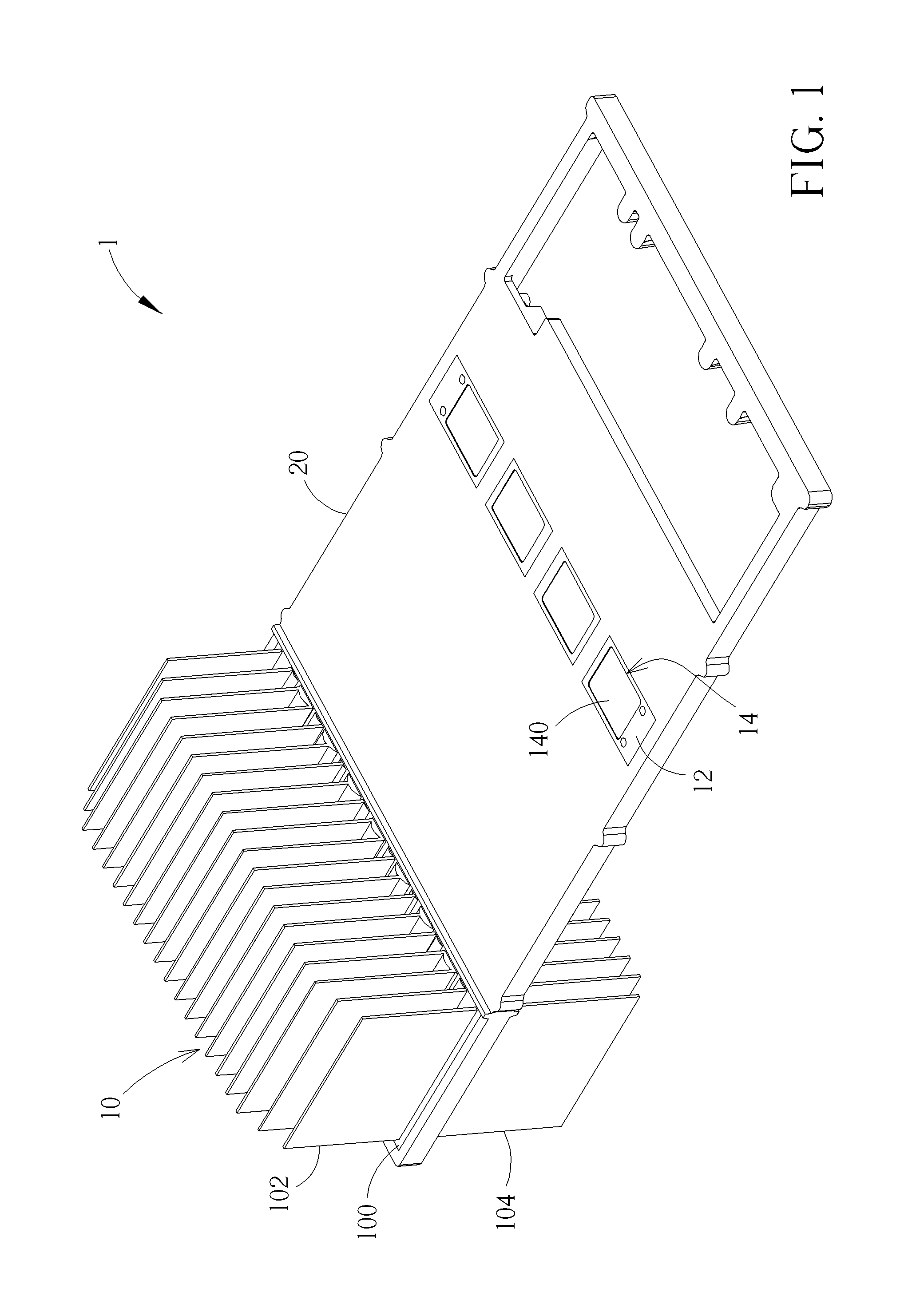
[0013]Referring to FIGS. 1 to 3, FIG. 1 is a schematic view illustrating a heat dissipating device 1 according to the invention, FIG. 2 is a schematic view illustrating the heat dissipating device 1 shown in FIG. 1 without the fourth base 20, and FIG. 3 is an exploded view illustrating the heat dissipating device 1 shown in FIG. 2. As shown in FIGS. 1 to 3, the heat dissipating device 1 comprises a heat dissipating fin module 10, a second base 12, a third base 14, a heat pipe 16, a first sleeve 18, a fourth base 20 and a second sleeve 22. It should be noted that the number of the third bases 14, the heat pipes 16, the first sleeves 18 and the second sleeves 22 can be determined based on practical applications, so those are not limited in the embodiment shown in FIGS. 1 to 3.

[0014]The heat dissipating fin module 10 is made of a first heat conducting material. The heat dissipating fin module 10 comprises a first base 100, a plurality of first heat dissipating fins 102 and a plurality ...

second embodiment

[0020]Referring to FIG. 4 along with FIG. 2, FIG. 4 is a schematic view illustrating a heat dissipating device 1′ according to the invention. The difference between the heat dissipating device 1′ and the aforesaid heat dissipating device 1 is that the heat dissipating fin module 10 of the heat dissipating device 1′ does not comprise the aforesaid second heat dissipating fins 104, and the holes 106 formed on the first base 100 are half circular in shape. As shown in FIG. 4, the first heat dissipating fins 102 extend from a side of the first base 100 and the heat dissipating segment 160 of the heat pipe 16 is embedded in the half circular holes 106. In practical applications, the heat dissipating segment 160 of the heat pipe 16 may be punched to form a flat bottom, so as to enable the flat bottom of the heat dissipating segment 160 to be coplanar with the bottom of the first base 100. Furthermore, the fourth base 20 may also be formed by the aforesaid die casting process, so it will n...


PUM


Abstract

A heat dissipating device includes a heat dissipating fin module, a second base, a third base, a heat pipe, a first sleeve and a fourth base. The heat dissipating fin module includes a first base and a plurality of first heat dissipating fins. A recess is formed on the second base. The third base is disposed in the recess. The heat pipe includes a heat dissipating segment, a heat absorbing segment and a connecting segment connecting the heat dissipating segment and the heat absorbing segment. The heat dissipating segment is disposed in the first base. The heat absorbing segment is disposed in the second and third bases and contacts the third base directly. The first sleeve at least covers the connecting segment. The fourth base is formed by a die casting process and covers peripheries of the first and second bases and the first sleeve.

Description

BACKGROUND OF THE INVENTION[0001]1. Field of the Invention[0002]The invention relates to a heat dissipating device and, more particularly, to a heat dissipating device capable of enhancing heat dissipating efficiency effectively.[0003]2. Description of the Prior Art[0004]Heat dissipating device is a significant component for electronic products. When an electronic product is operating, the current in circuit will generate unnecessary heat due to impedance. If the heat is accumulated in the electronic components of the electronic product without dissipating immediately, the electronic components may get damage due to the accumulated heat. Therefore, the performance of heat dissipating device is a significant issue for the electronic product. How to enhance heat dissipating efficiency of the heat dissipating device effectively has become a significant design issue.SUMMARY OF THE INVENTION[0005]The invention provides a heat dissipating device capable of enhancing heat dissipating effic...

Claims


Application Information

Patent Timeline
Patent Type & Authority Patents(United States)
IPC IPC(8): F28D15/00F28D15/02H01L23/427
CPCF28D15/0275F28D15/02H01L23/427H01L23/3672H01L2924/0002F28F3/02F28F1/22H01L2924/00
Inventor LIN, CHIA-YU
Owner COOLER MASTER DEVELOPMENT CORP
Why Eureka
Try Eureka