Light emitting module

a technology of light emitting modules and light shielding walls, which is applied in the direction of fixed installation, transportation and packaging, lighting and heating equipment, etc., can solve the problems of variance in the height of each light shielding wall, thickness, and the inability to form the desired light distribution pattern, etc., to achieve clear cutoff lines, increase the quantity of light, and facilitate fabrication

Inactive Publication Date: 2016-05-24
KOITO MFG CO LTD
View PDF14 Cites 2 Cited by
  • Summary
  • Abstract
  • Description
  • Claims
  • Application Information

AI Technical Summary

Benefits of technology

[0014]According to the invention described under (1) above, part of the light emitted from the semiconductor light emitting element is internally reflected in the transparent resin, and the light which is internally reflected in the transparent resin is reflected on the light shielding wall to thereby increase the quantity of light at the distal end portion of the light shielding wall. Therefore, the difference between the quantity of light shone from the distal end portion of the light shielding wall and the quantity of light shone from the other portions than the distal end portion of the light shielding wall is reduced, thereby making it possible to form a clear cutoff line in the light distribution pattern.
[0015]According to the invention described under (2) above, the luminous intensity of the light distribution pattern formed by light emitted from the plurality of semiconductor light emitting elements can be made uniform, and a clear cutoff line can be formed.
[0016]According to the invention described under (3) above, light which is internally reflected in the transparent resin to be reflected on the exposed surface of the light shielding wall is increased, and therefore, the quantity of light which is shone from the distal end portion of the light shielding wall and the quantity of light which is shone from the other portions than the distal end portion of the light shielding wall become even, thereby making it possible to form a far clearer cutoff line in the light distribution pattern.
[0017]According to the invention described under (4) above, the transparent resin can be applied simultaneously in the step where the bonding resin is applied, and therefore, the light emitting module can easily be fabricated, and a reduction in the fabrication time of the light emitting module can be realized.

Problems solved by technology

However, there exists a possibility that there are caused variances in height of each light shielding wall, thickness of each semiconductor light emitting element and thickness of the adhesive due to machining or working accuracy in the production process of the light emitting module.
In the light emitting module described in Patent Literature 1, as described above, since the quality of light shone after having been reflected at the distal end portion of the light shielding wall is smaller than the quantity of light which is shone from the other portions than the distal end portion of the light shielding wall, the cutoff line in the light distribution pattern becomes unclear, leading to a problem that a desired light distribution pattern cannot be formed.

Method used


Image

  • Light emitting module
  • Light emitting module
  • Light emitting module

Examples


Embodiment Construction

[0023]Hereinafter, referring to the accompanying drawings, a mode for carrying out a light emitting module of the invention will be described.

[0024]In a form which will be described below, a light emitting module of the invention is applied to a light emitting module which is provided in a vehicle headlamp. It is noted that the application of the light emitting module of the invention is not limited the light emitting module provided in the vehicle headlamp and hence that the invention can also widely be applied to other various types of vehicle lamps than the vehicle headlamp.

[0025]A vehicle headlamp 1 is disposed mounted at each of left- and right-hand end portions of a front end portion of a vehicle body.

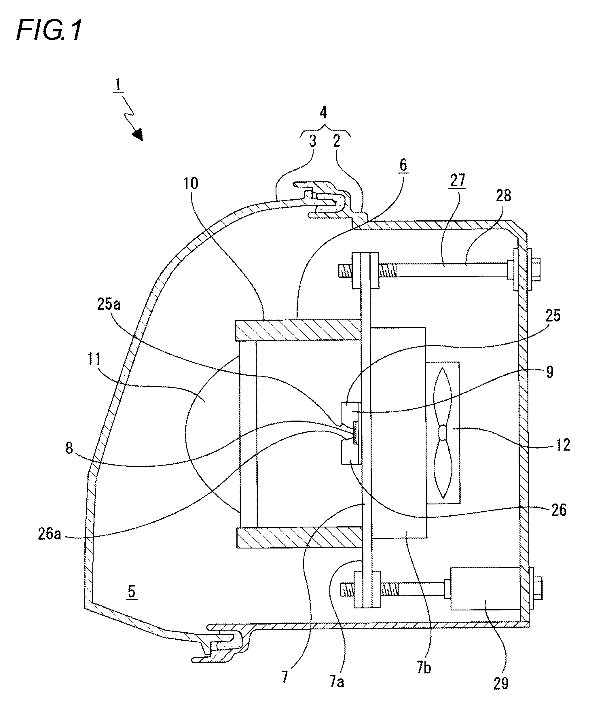
[0026]As shown in FIG. 1, the vehicle headlamp 1 includes a lamp housing 2 which is formed into a concave shape which is opened to the front and a cover 3 which closes an opening side of the lamp housing 2, and a lamp outer housing 4 is made up of the lamp housing 2 and the cover...


PUM


Abstract

There are provided a light emitting module including a luminescent material layer (15) which is disposed so as to cover a light emitting surface (13a) of a semiconductor light emitting element (13) and which changes a wavelength of at least part of light emitted from the semiconductor light emitting element, and a light shielding wall (16) which surrounds the semiconductor light emitting element and the luminescent material layer from the circumference thereof, and the luminescent material layer is bonded to the semiconductor light emitting element and the light shielding wall with a bonding resin (23) having a light transmittivity, a distal end portion of the light shielding wall is caused to project further forwards than the luminescent material layer, and a transparent resin (24) is applied so as to cover an exposed surface (20a) of a distal end portion (21) of the light shielding wall.

Description

TECHNICAL FIELD[0001]The present invention relates to a light emitting module. The invention relates more particularly to a technical field in which a transparent resin is applied to distal end portions of light shielding walls which surround a semiconductor light emitting element from the circumference thereof to thereby form a clear cutoff line in a light distribution pattern.BACKGROUND ART[0002]There are light emitting modules which employ a semiconductor light emitting element such as a light emitting diode (LED) as a light source, and these light emitting modules are equipped, for example, in vehicle lamps which shine light emitted from the semiconductor light emitting element as illumination light. In these vehicle lamps, a predetermined light distribution pattern is formed by light shone as illumination light.[0003]In these light emitting modules, there are some light emitting modules which has a plurality of semiconductor light emitting elements which shine light, a circuit ...

Claims


Application Information

Patent Timeline
Patent Type & Authority Patents(United States)
IPC IPC(8): H01L33/54F21S8/10F21W107/10H01L25/075H01L33/44H01L33/50H01L33/52H01L33/58
CPCF21S41/143F21S41/24F21S41/285F21S41/32F21S41/321F21S41/322F21S41/151F21S41/153F21S41/176F21S45/435H01L33/44H01L33/507H01L2224/17H01L2924/0002F21S45/43H01L25/0753H01L33/54H01L33/58H01L2933/0058H01L33/52H01L2924/00
Inventor MAEDA, SHINPEITOKIDA, TSUKASA
Owner KOITO MFG CO LTD
Why Eureka
Try Eureka