
Computing cloud in a wireless telecommunication system

a wireless telecommunication system and computing cloud technology, applied in the field of mobile telecommunication, can solve the problems of inability to adapt to real-time communication, high risk of radio failure, unwanted disconnections of mobile devices, etc., and achieve the effect of reducing the processing capacity of base stations

Active Publication Date: 2016-05-24
ALCATEL LUCENT SAS
View PDF13 Cites 1 Cited by
  • Summary
  • Abstract
  • Description
  • Claims
  • Application Information

AI Technical Summary

Benefits of technology

The present invention provides an improved method for communication in a wireless telecommunication system. It introduces a computing cloud that can perform non-time-critical operations for the base stations in the system, reducing the processing capacity requirements. The non-time-critical operations are performed by a pool of computing resources that are centrally located and connected to each other. This helps to minimize costs and base station sizes. The invention also provides a means for balancing peak loads across cells and improving overall traffic load processing. The computing cloud is adaptable to perform the non-time-critical operations of the plurality of base stations, further reducing processing capacity requirements. Overall, the invention helps to optimize wireless communication efficiency and save costs.

Problems solved by technology

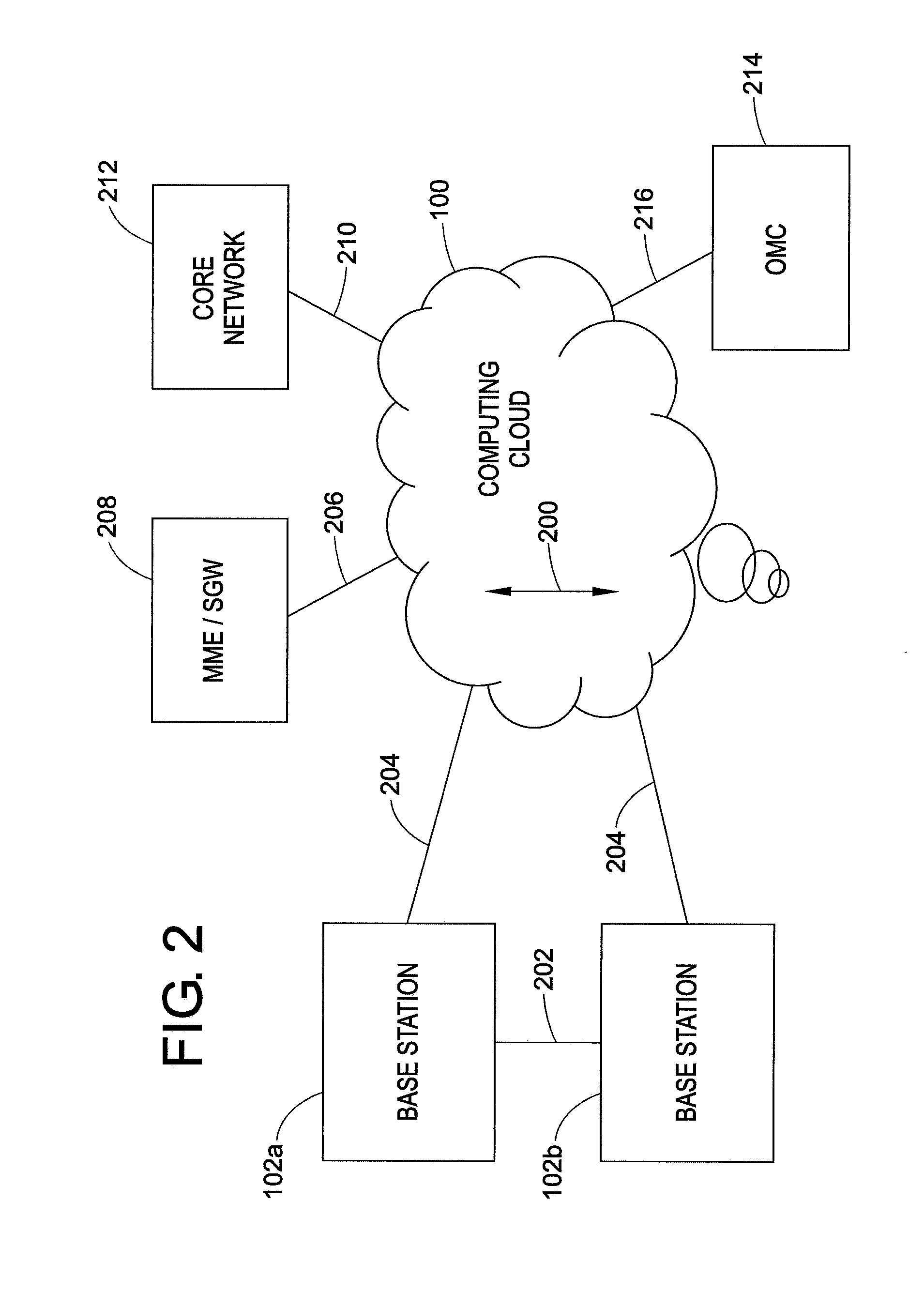
Additionally or alternatively other connections can be used that are not adapted for real-time communication because the computing cloud only performs non-time-critical operations.
This time delay could be too high for time critical operations.
In general, time critical operations are operations where an induced additional delay because of signal transmission from the base stations to the computing cloud and vice versa corresponds to a high risk of radio failures and unwanted disconnections of mobile devices.

Method used


Image

  • Computing cloud in a wireless telecommunication system
  • Computing cloud in a wireless telecommunication system
  • Computing cloud in a wireless telecommunication system

Examples


Embodiment Construction

[0038]Like numbered elements in these Figs. are either identical elements or perform the same function. Elements which have been discussed previously will not necessarily be discussed in later Figs. if the function is identical.

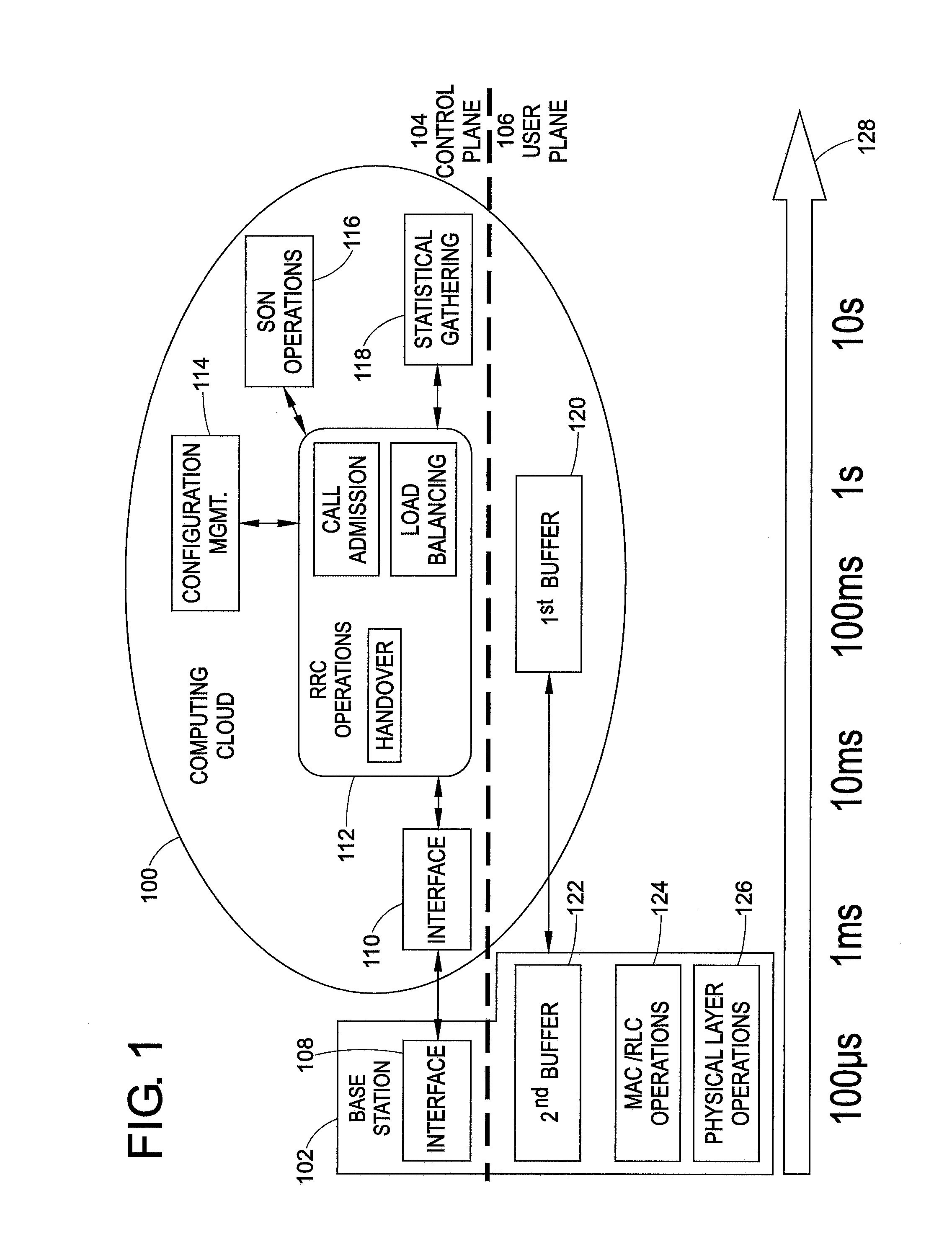
[0039]FIG. 1 is a schematic view of a computing cloud 100 and a base station 102. The computing cloud 100 comprises several computing units such as servers or computers. The base station 102 is located outside the computing cloud 100. FIG. 1 is separated into a control plane 104 and a user plane 106. The computing cloud 100 and the base station 102 both have means being located in the control plane 104 and means being located in user plane 106.

[0040]The base station 102 is connected to the computing cloud 100 via interfaces 108 and 110. Interface 108 is located in base station 102 and interface 110 is located in computing cloud 100. Both interfaces 108 and 110 are located in the control plane 104.

[0041]The computing cloud 100 comprises several means for perfo...


PUM


Abstract

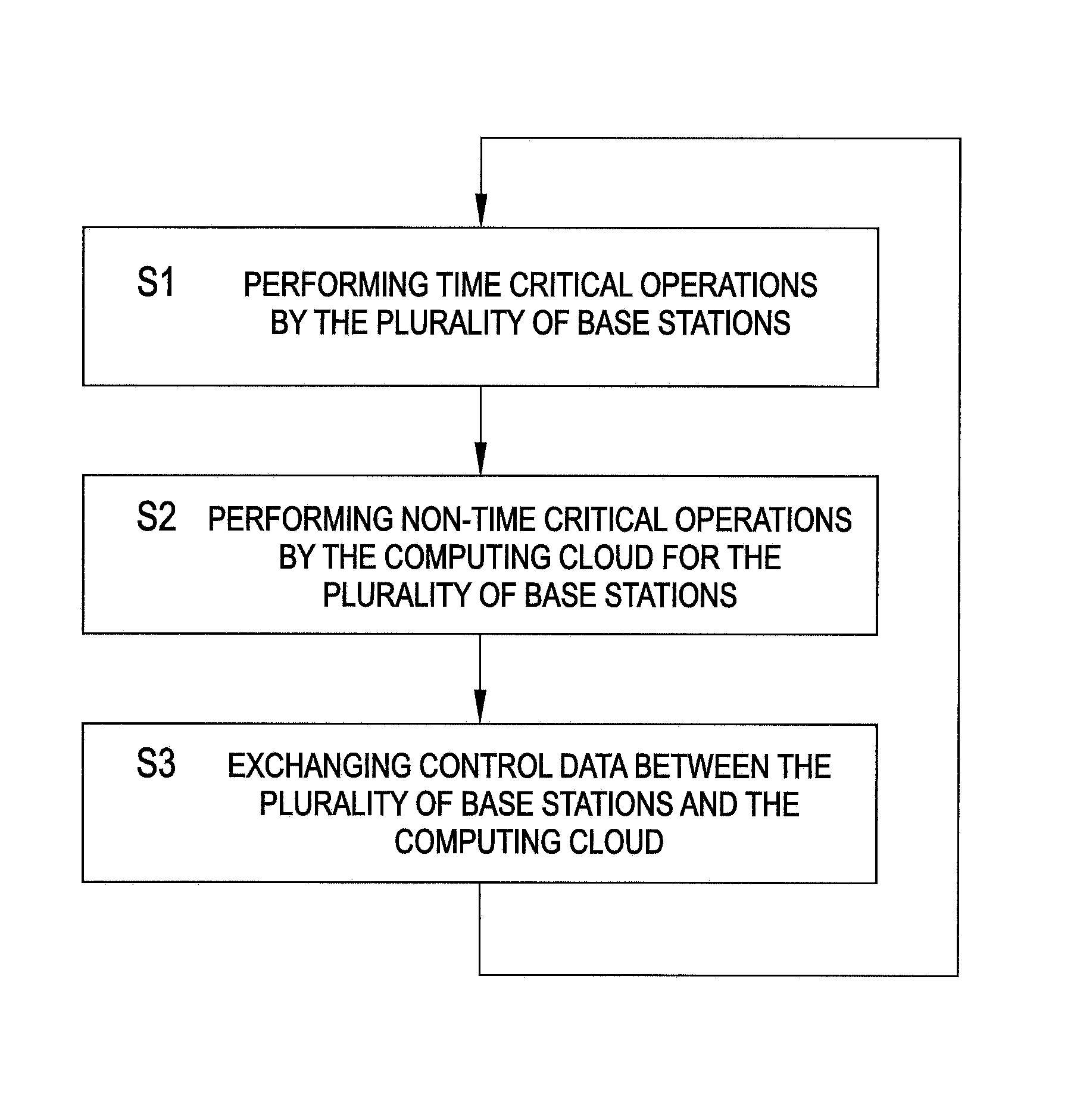
The invention relates to a method for communication in a wireless telecommunication system, wherein the wireless telecommunication system comprises a plurality of base stations (102) and at least one computing cloud (100), wherein the plurality of base stations are each connected to the at least one computing cloud, wherein the computing cloud comprises a plurality of computing devices, wherein the computing cloud is operatively coupled to the plurality of base stations, and wherein the method comprises the following steps: performing (S1) time-critical operations by the plurality of base stations; performing (S2) non-time-critical operations by the at least one computing cloud for the plurality of base stations; and exchanging (S3) control data between the plurality of base stations and the at least one computing cloud; wherein the non-time-critical operations comprise at least one of the following operations: handover procedures, call admissions, load balancing, gathering statistical data of cells of the wireless telecommunication system, configuration management for the cells of the wireless telecommunication system, and operations for self organizing functions of the wireless telecommunication system, and wherein the control data is used by the computing cloud for performing the non-time-critical operations.

Description

FIELD OF THE INVENTION[0001]The invention relates to the filed of mobile telecommunication, in particular to a wireless telecommunication system comprising a computing cloud.BACKGROUND AND RELATED ART[0002]The majority of operations performed by a wireless telecommunication system is performed by the base stations of the wireless telecommunication system. For example handovers are initiated and performed by the base stations, call admissions are performed by the base stations, load balancing is performed by the base stations, statistical data is gathered by the base stations and the cells of the wireless telecommunication system are configured by the base stations.[0003]US 2011 / 0014918 A1 describes a cellular communication system supported by first physical layer processes, second layer user plane control processes and third layer control plane control processes. The first layer process is executed in a base station. A distribution controller allocates the layer processes such that ...

Claims


Application Information

Patent Timeline
Patent Type & Authority Patents(United States)
IPC IPC(8): H04L1/00H04W16/02H04W72/04G06F9/50H04W36/02H04L29/08H04W28/08
CPCH04W16/02G06F9/5072H04L67/10H04W36/023H04W72/0406G06F2209/509H04W28/08H04W36/08H04W72/20
Inventor BAKKER, HAJOMAYER, HANS-PETERDOETSCH, UWE
Owner ALCATEL LUCENT SAS
Learn More