
Method of making reduced backlash joint

a backlash joint and joint technology, applied in the direction of driving chains, couplings, surgical forceps, etc., can solve the problems of over- or under-compensation or other imprecise activation motions of the user, backlash between the connecting joint components, accidents or sloppiness in a remotely-actuated surgical procedure, etc., to reduce the need for expensive, precision machining, and prevent or diminish unwanted vibrations.

Active Publication Date: 2016-06-07
CAREFUSION 2200 INC
View PDF8 Cites 2 Cited by
  • Summary
  • Abstract
  • Description
  • Claims
  • Application Information

AI Technical Summary

Benefits of technology

The present invention allows for the creation of precise fit joints, such as in drive chains for remote actuation, without the need for expensive precision machining. It also prevents or reduces vibration and imprecision in couplings, resulting in a more robust and precise joint at a lower cost.

Problems solved by technology

One problem that can occur with such drive chains when certain fit is not close is called “backlash.” Backlash between connecting joint components, for example links in a chain, can occur when the joint or chain is pushed or pulled for mechanical actuation, or generally when a mechanical component is actuated, for example in rotary or linear motion, or in the case of a universal joint in complex multi-axis motion.
In particular, fitting issues or “give” between joint components or links / connection components such as might be used, for example, in an actuating chain, can cause such backlash when the joint components or links / connection components are used to transmit force.
For example, in a surgical use, backlash in the push or pull of a joint components or links / connection components in an actuating chain that controls end effectors or tools in a remotely actuated surgical device during surgery may cause imprecise movements, resulting in over- or under-compensation or other imprecise activating motions on the part of the user.
Such over- or under-compensation, or other imprecise activating motion, may lead to accidents or sloppiness in a remotely-actuated surgical procedure.
Moreover, “give” in the joint or chain makes its motion less intuitive for the user and, therefore, less easily and precisely controlled, making precision work more difficult.
Although precision machining of components of such chains can, in some cases, improve precision actuation, such machining is often expensive and difficult.
It can be especially difficult to machine, with precision, mating surfaces on chain links that are often responsible for the “give” or backlash effect described above.
Fitting issues may occur between the mating surfaces of links with other portions, including the metal pins.

Method used


Image

  • Method of making reduced backlash joint
  • Method of making reduced backlash joint
  • Method of making reduced backlash joint

Examples


Embodiment Construction

[0047]Aspects of the present invention will now be described more fully hereinafter with reference to the accompanying drawings, in which variations and aspects of the present invention are shown. Aspects of the present invention may, however, be realized in many different forms and should not be construed as limited to the variations set forth herein; rather, the variations are provided so that this disclosure will be thorough and complete in the illustrative implementations, and will fully convey the scope thereof to those skilled in the art.

[0048]Unless otherwise defined, all technical and scientific terms used herein have the same meaning as commonly understood by one of ordinary skill in the art to which aspects of the present invention belong. The methods and examples provided herein are illustrative only and not intended to be limiting.

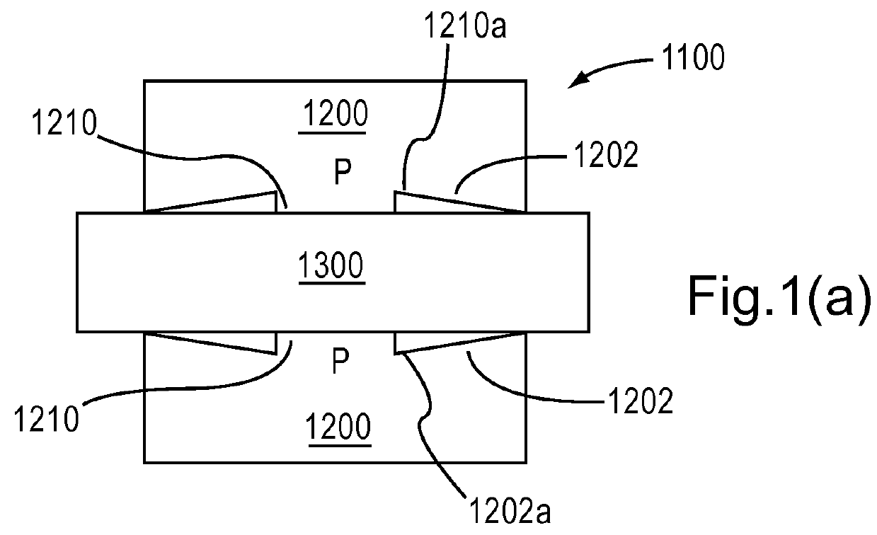
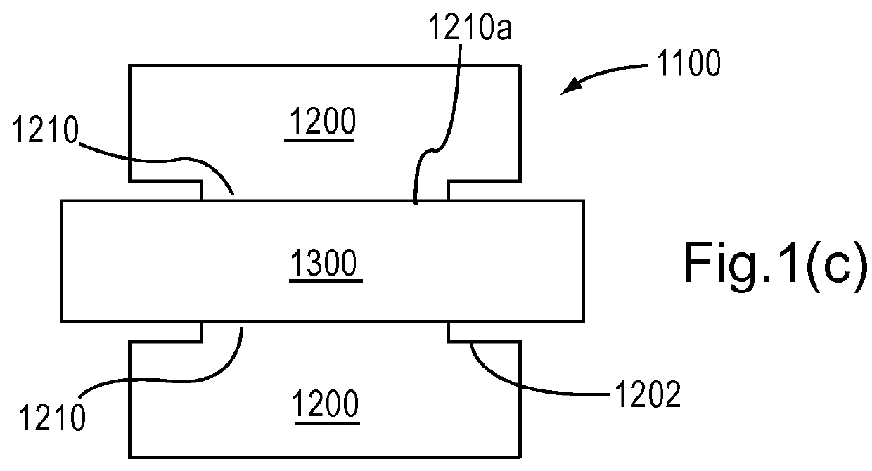
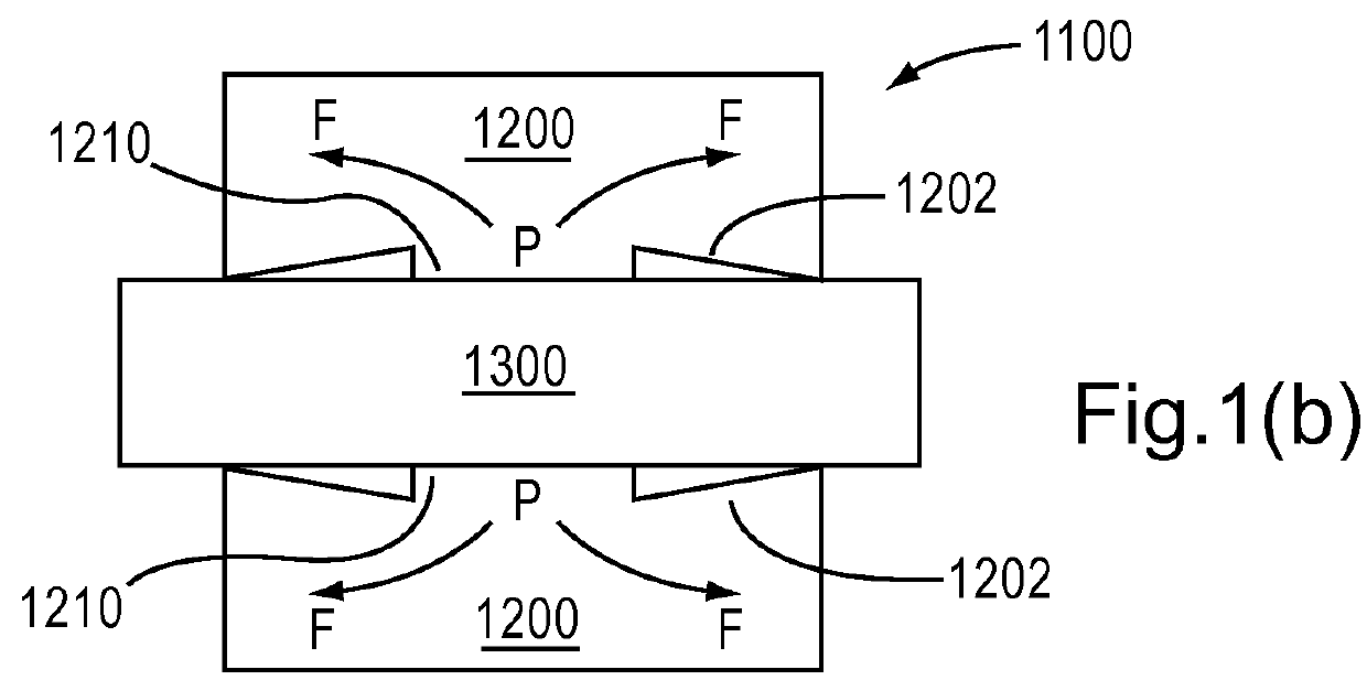
[0049]FIG. 1(a) is an overview of a process of precision-fitting a joint or component, in accordance with aspects of the present invention. FI...


PUM

PropertyMeasurementUnit
areaaaaaaaaaaa
glass transition temperatureaaaaaaaaaa
melting temperatureaaaaaaaaaa

Abstract

A joint and a corresponding method of creating a precision-fit joint, including creating a mating surface on a first joint component so that the mating surface includes one or more interfering features, connecting a second joint component with the mating surface such that the interfering feature is compressed, and heating the mating surface above a glass transition temperature or melting temperature of the mating surface, or otherwise treating the surface, so as to induce flow of material from the interfering feature to a area of relatively low pressure between the first joint component and the second joint component.

Description

CROSS-REFERENCE TO RELATED APPLICATIONS[0001]This application is a National Stage entry of International Application No. PCT / US2011 / 039402, filed Jun. 7, 2011, which claims priority to U.S. Provisional Appl. No. 61 / 354,042 filed on Jun. 11, 2010. This application is also related to Applicant's co-pending PCT Appl. No. PCT / US1OI46,619 titled “ARTICULATED SURGICAL TOOL” filed on Aug. 25, 2010, co-pending PCT Appl. No. PCTIUS2OI 1 / 022562 titled “OVERFORCE MECHANISM” filed Jan. 26, 2011, and is related to co-pending PCT Appl. No. PCT / US2OII / 022086 titled “HYDRAULIC DEVICE INCLUDING A SPOOL VALVE” filed Jan. 21, 2011, the entirety of each of which is hereby incorporated by reference herein.BACKGROUND[0002]1. Field of the Invention[0003]Aspects of the present invention relate to a reduced backlash joint, and a method of making same.[0004]2. Background of the Related Art[0005]Mechanisms for transmitting mechanical force, particularly those transmitting force around corners and bends, often...

Claims


Application Information

Patent Timeline
Patent Type & Authority Patents(United States)
IPC IPC(8): F16G13/00F16G13/02F16G13/10A61B17/00F16G13/08F16D3/42B21L11/00A61B17/34
CPCA61B17/00B21L11/00F16D3/42F16G13/02F16G13/08F16G13/10A61B2017/00314A61B2017/00526A61B2017/3409B23P2700/11F16D2250/00Y10T29/49826Y10T29/49865Y10T29/49936A61B34/30A61B34/37A61B2034/305A61B17/2816A61B2017/2947B23P11/00
Inventor DOYLE, MARK
Owner CAREFUSION 2200 INC
Features
  • Generate Ideas
  • Intellectual Property
  • Life Sciences
  • Materials
  • Tech Scout
  • Unparalleled Data Quality
  • Higher Quality Content
  • 60% Fewer Hallucinations
Learn More