
Optical Communication System and Method for Generating Dark Return-to-Zero and DWDM Optical MM-Wave Generation for ROF Downstream Link Using Optical Phase Modulator and Optical Interleaver

Inactive Publication Date: 2007-07-19
NEC CORP
View PDF11 Cites 18 Cited by
  • Summary
  • Abstract
  • Description
  • Claims
  • Application Information

AI Technical Summary

Benefits of technology

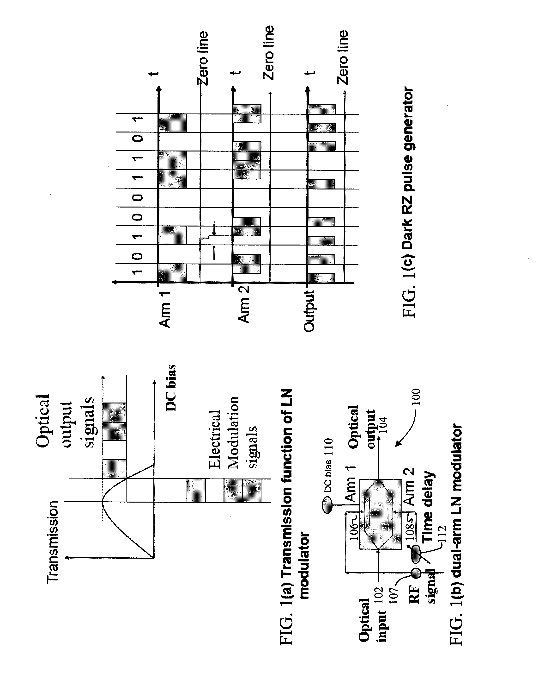
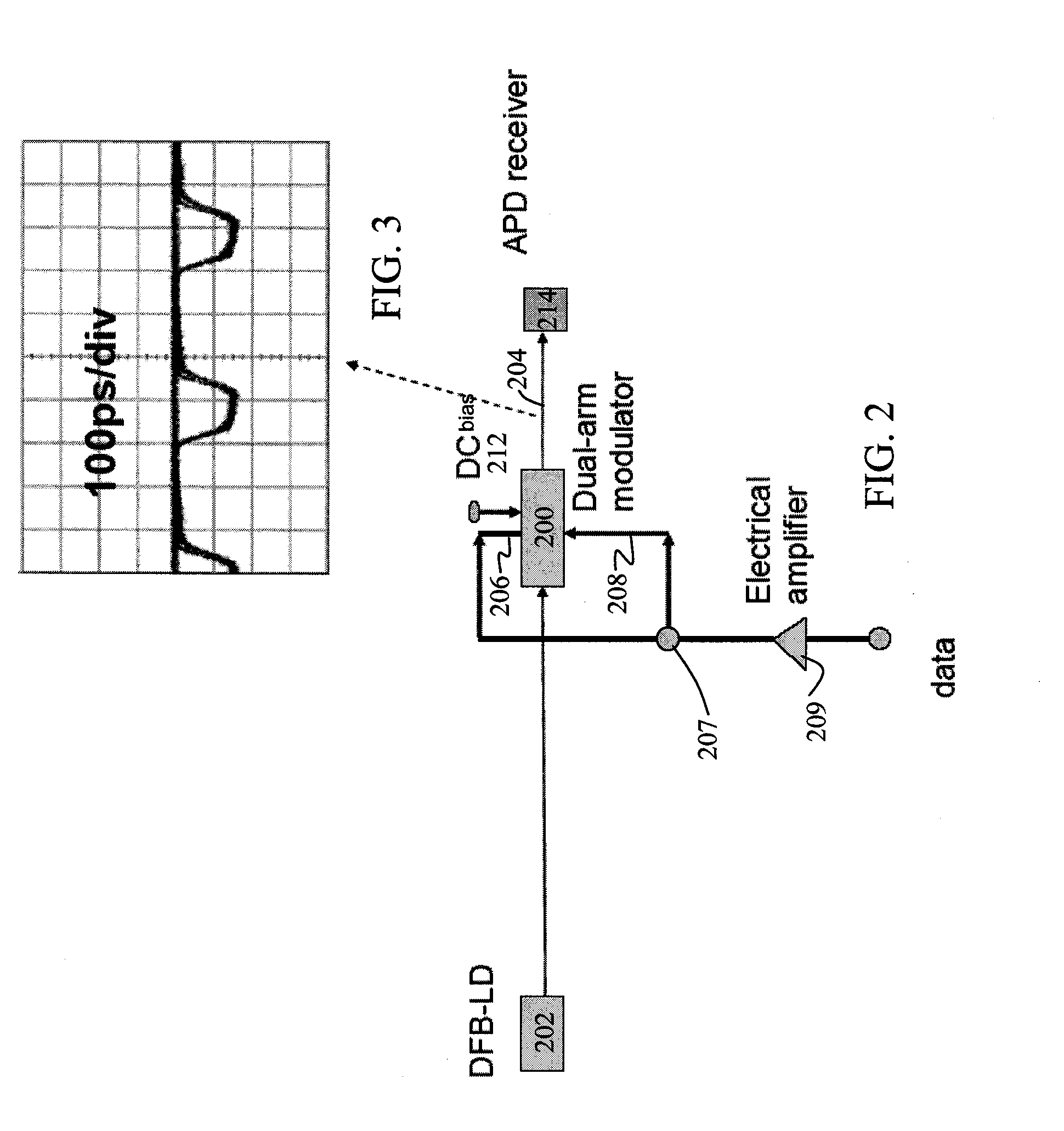
[0005] In accordance with a first aspect of the invention, there is provided a method of generating a dark-RZ pulse in an optical communications system with a dual-arm modulator having first and second arms, where the modulator is driven by RF signals on each arm, comprising the steps of: setting a direct current bias on the modulator to a specific value such that an output optical power from the modulator achieves a maximum value when the RF signals on the first and second arms of the modulator are off; maintaining the direct current bias at the specific value and applying RF signals to the first and second arms of the modulator; and delaying one of the RF signals applied to one of the first and second arms relative to the other of the RF signals such that a dark-RZ pulse is generated with a duty cycle based on the delay. This methodology provides an economical solution for dark-RZ pulse generation which advantageously employs a single intensity modulator, electrical amplifier and electrical phase shifter. This methodology further provides for the generation of any duty cycle and extinction ratio dark-RZ pulse.
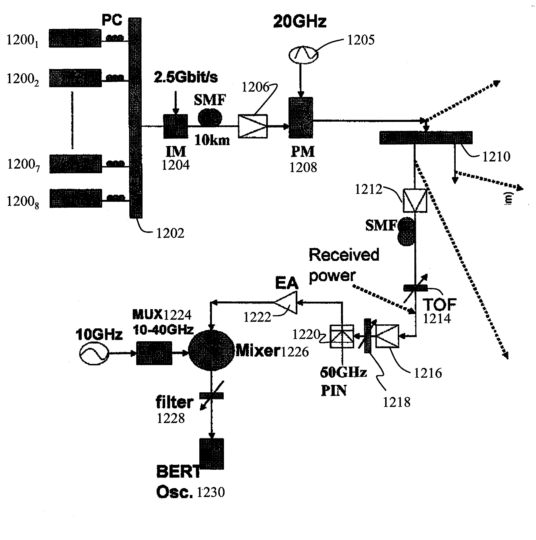
[0006] In accordance with another aspect of the invention, a method is provided for generating dense wave division multiplexing (DWDM) optical mm-waves in an optical transmission system. The method comprising the steps of: generating a plurality of CW lightwaves to produce individual wavelength signals with a specified channel spacing; multiplexing the CW lightwaves into a multiplexed DWDM optical signal; intensity modulating the multiplexed DWDM optical signal; phase modulating the intensity modulated DWDM optical signal to produce a phase modulated DWDM optical signal; applying the phase modulated DWDM optical signal to an input port of an optical interleaver, the optical interleaver having a specified bandwidth to suppress the optical carriers and convert the DWDM optical signal to DWDM optical mm-waves; and amplifying the DWDM optical mm-waves and transmitting the DWDM optical mm-waves over single mode fiber (SMF). This methodology advantageously avoids the need to employ a DC bias controller. A relatively small RF signal is employed to drive the phase modulator thereby preventing the generation of higher-order sidebands and limiting the need for dispersion compensation.

Problems solved by technology

Obviously, the key issue for this orthogonal modulation scheme is to generate a dark-RZ pulse.
It is well known that it is difficult to have stable operations using a NOLM and that the NOLM has a high-power consumption.
This consequently increases costs.
This configuration is complex and expensive.
However, due to the multiple sidebands created by a deep modulation index, the mm-wave generated by this methodology suffered from excessive fiber dispersion, and the transmission distance was thus limited to a few kilometers.
Greater distances require dispersion compensation for such radio over fiber (ROF) systems, thereby increasing costs and reducing flexibility of dynamic systems where transmission distances to customer premises over access networks may not be fixed.

Method used


Image

  • Optical Communication System and Method for Generating Dark Return-to-Zero and DWDM Optical MM-Wave Generation for ROF Downstream Link Using Optical Phase Modulator and Optical Interleaver
  • Optical Communication System and Method for Generating Dark Return-to-Zero and DWDM Optical MM-Wave Generation for ROF Downstream Link Using Optical Phase Modulator and Optical Interleaver
  • Optical Communication System and Method for Generating Dark Return-to-Zero and DWDM Optical MM-Wave Generation for ROF Downstream Link Using Optical Phase Modulator and Optical Interleaver

Examples


Embodiment Construction

[0033] Embodiments of the invention will be described with reference to the accompanying drawing figures wherein like numbers represent like elements throughout. Before embodiments of the invention are explained in detail, it is to be understood that the invention is not limited in its application to the details of the examples set forth in the following description or illustrated in the figures. The invention is capable of other embodiments and of being practiced or carried out in a variety of applications and in various ways. Also, it is to be understood that the phraseology and terminology used herein is for the purpose of description and should not be regarded as limiting. The use of “including,”“comprising,” or “having” and variations thereof herein is meant to encompass the items listed thereafter and equivalents thereof as well as additional items.

[0034] In accordance with a first aspect of the invention, an economical solution for dark-RZ pulse generation is shown and descr...


PUM


Abstract

A method of generating a dark-RZ pulse in an optical communications system with a dual-arm modulator by setting a direct current bias on the modulator to a specific value such that an output optical power from the modulator achieves a maximum value when the RF signals on the first and second arms of the modulator are off and maintaining the direct current bias at the specific value and applying RF signals to the first and second arms of the modulator and delaying one of the RF signals applied to one of the first and second arms relative to the other of the RF signals such that a dark-RZ pulse is generated with a duty cycle based on the delay. Another aspect of the invention provides a method for generating dense wave division multiplexing (DWDM) optical mm-waves in an optical transmission system by phase modulated DWDM optical signal and applying the phase modulated DWDM optical signal to an input port of an optical interleaver, the optical interleaver having a specified bandwidth to suppress the optical carriers and convert the DWDM optical signal to DWDM optical mm-waves; and amplifying the DWDM optical mm-waves and transmitting the DWDM optical mm-waves over single mode fiber (SMF).

Description

CROSS REFERENCE TO RELATED APPLICATIONS [0001] This non-provisional application claims the benefit of U.S. Provisional Application Ser. No. 60 / 746,383 entitled “Optical Communication System and Method for Generating Dark Return-to-Zero Signal,” filed May 4, 2006, and U.S. Provisional Application Ser. No. 60 / 743,123, entitled “A DWDM Optical Mm-wave Generation for ROF Downstream Link Using Optical Phase Modulator and Optical Inter-leaver,” filed Jan. 12, 2006, the contents of which are hereby incorporated by reference herein in their entirety.FIELD OF THE INVENTION [0002] The present invention relates generally to optical networking, and more particularly, to a methodology of generating a dark RZ pulse using a single intensity modulator, electrical amplifier and phase shifter, and a novel scheme to improve the stability of dense wavelength division multiplexing (DWDM) wave generation without a DC-bias controller. BACKGROUND OF THE INVENTION [0003] In order to increase spectral effici...

Claims


Application Information

Patent Timeline
IPC IPC(8): H04B10/04
CPCH04B10/2575H04B10/505H04J14/0256H04J14/02H04B10/508
Inventor YU, JIANJUNXU, LEIJI, PHILIPWANG, TING
Owner NEC CORP
Learn More