Multi-band LTE antenna

a multi-band lte antenna and antenna technology, applied in the direction of resonant antennas, antenna earthings, protective materials, etc., can solve the problems of difficult design of multi-band lte antennas, and achieve the effects of good return loss, wide bandwidth, and compact siz

Active Publication Date: 2016-06-07
AIRGAIN INC
View PDF91 Cites 11 Cited by
  • Summary
  • Abstract
  • Description
  • Claims
  • Application Information

AI Technical Summary

Benefits of technology

[0022]The present invention provides a solution to the needs of the LTE mobile device market in the form of a multi-band antenna. This surface-mounted multi-band LTE antenna has compact size, wide bandwidth, good return loss, high gain and high radiation efficiency, and no matching circuit is needed. The multi-band LTE / WLAN chip antenna of the present invention meets the needs of market: 698-960 MHz (LTE700 / 800 / 850 / 900) and 2400-2500 GHz (WLAN 2 G).
[0023]In the present invention, a surface-mounted multi-band LTE antenna with high gain and high efficiency for wireless communication devices applications is presented. The radiation efficiency is greater than 60% respectively in all frequency bands it covered. In addition, since the antenna is built with PCB, it is easy for high volume production and to build high gain array antennas.

Problems solved by technology

However, in most cases the design of multi-band LTE antenna is very difficult, especially when the LTE700 / 800 / 900 bands are included, since it is very hard to get enough bandwidth with good return loss for each frequency band.
For wireless communication devices applications, there are generally three challenging requirements for embedded antenna: good performance, compact size and low cost.

Method used


Image

  • Multi-band LTE antenna
  • Multi-band LTE antenna
  • Multi-band LTE antenna

Examples


Embodiment Construction

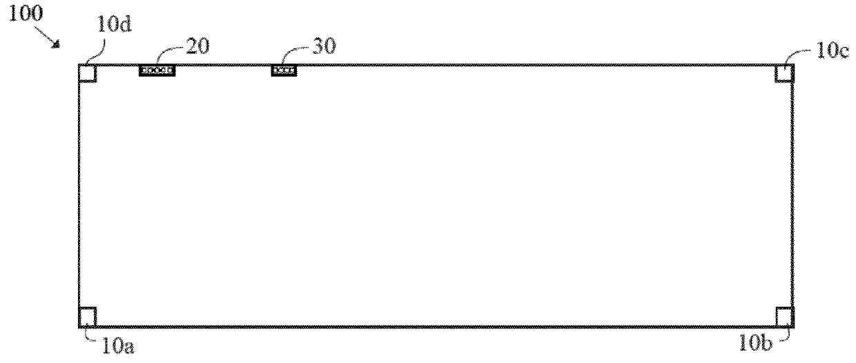
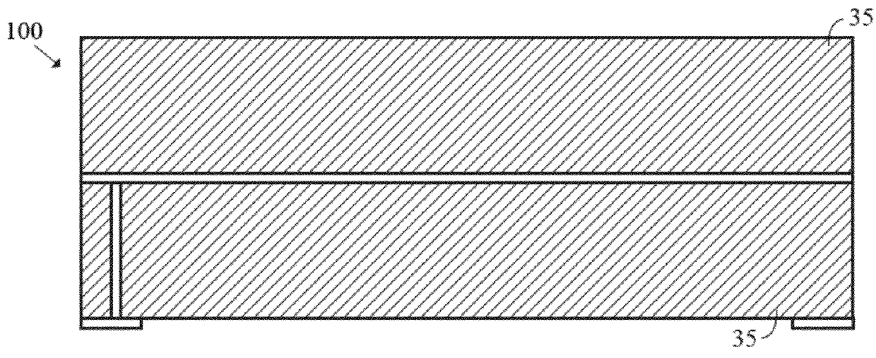
[0043]The multi-band LTE antenna of the present invention is preferably a surface mount type antenna structure, and is easy to mount on customer circuit PCB by a surface-mount technology (SMT) process. The architecture of the surface-mounted multi-band LTE antenna is shown in FIG. 1 through FIG. 3, and the multi-band LTE antenna, prior to mounting, is shown in FIG. 4 through FIG. 7. The antenna is sealed in the middle layer of two 60 mil FR4 PCBs 35, shown in the antenna side view FIG. 2, and six pins are exposed, shown in the antenna bottom view FIG. 1B. FR-4 is a woven glass and epoxy dielectric material for a PCB.

[0044]The six pins comprise a feeding pin 30, a grounding pin 20, and four floating pins 10a-10d that are mainly used for increasing the soldering strength on the PCB. The four floating pins 10a-10d have a certain influence on antenna performance. The antenna is connected to RF front-end circuit of a wireless communication device either with a 50 ohm micro-strip line or ...


PUM


Abstract

A surface-mounted multi-band LTE antenna that covers the frequency band of 698-960 MHz (LTE 700 / 800 / 900 bands) and 2400-2500 GHz (WLAN 2.4G band) is disclosed herein. The antenna preferably has high gain and high radiation efficiency, and is used for a variety of wireless communication devices applications. The surface-mounted multi-band LTE antenna has compact size, wide bandwidth, good return loss, high gain and high radiation efficiency, and no matching circuit is needed.

Description

CROSS REFERENCES TO RELATED APPLICATIONS[0001]The Present Application claims priority to U.S. Provisional Application No. 61 / 826,981, filed May 23, 2013, and is a continuation-in-part application of U.S. patent application Ser. No. 29 / 457,103, filed on Jun. 6, 2013, both of which are hereby incorporated by reference in their entireties.STATEMENT REGARDING FEDERALLY SPONSORED RESEARCH OR DEVELOPMENT[0002]Not ApplicableBACKGROUND OF THE INVENTION[0003]1. Field of the Invention[0004]The present invention generally relates to antennas. More specifically, the present invention relates to the architecture of a surface-mounted multi-band LTE antenna that covers the frequency band of 698-960 MHz (LTE 700 / 800 / 900 bands) and 2400-2500 MHz (WLAN 2.4 G band). The antenna has high gain and high radiation efficiency, and is used for a variety of wireless communication devices applications.[0005]2. Description of the Related Art[0006]The prior art discusses various antennas.[0007]Current wireless ...

Claims


Application Information

Patent Timeline
Patent Type & Authority Patents(United States)
IPC IPC(8): H01Q5/00
CPCH01Q5/001H01Q1/243H01Q1/40H01Q9/0421H01Q9/42H01Q5/364H01Q5/10H01Q1/242H01Q1/48H01Q1/50H01Q15/14
Inventor HE, ZIMING
Owner AIRGAIN INC
Why Eureka
Try Eureka