

Apparatus and method for moving and activating an active agent
a technology of active agents and apparatus, applied in the field of apparatus and methods for moving and activating active agents, can solve the problems of difficult planning step to exactly, difficulty in local limited medication, so as to achieve non-invasive and accurate treatment
- Summary
- Abstract
- Description
- Claims
- Application Information
AI Technical Summary
Benefits of technology
Problems solved by technology
Method used
Image

Examples
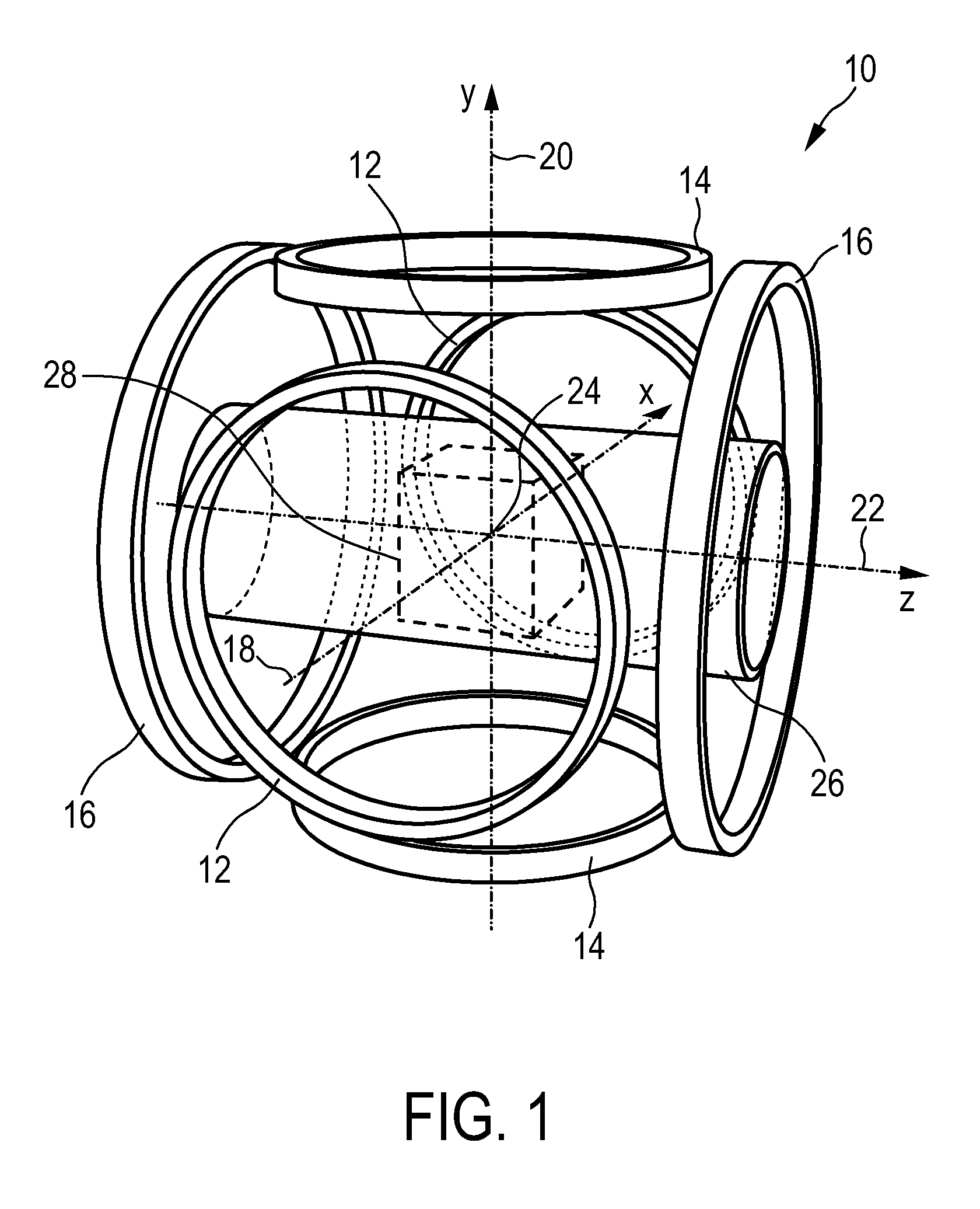
embodiment 10
[0061]The embodiment 10 of the MPI scanner may include one further pair, preferably three further pairs, of parallel circular coils, again oriented along the x-, y-, and z-axes. These coil pairs, which are not shown in FIG. 1, serve as receive coils. These receive coils are only needed in the present invention if receiving signals have to be acquired and the acquired data needs to be imaged. This is however not always the case, since moving and placing the target element and activating the active agent are the main purposes of the present invention.
[0062]However, if receiving coils are provided, the magnetic field generated by a constant current flowing through one of these receive coil pairs is spatially nearly homogeneous within the field of view and parallel to the axis of the respective coil pair. The receive coils are supposed to be well decoupled. The time dependent voltage induced in a receive coil is amplified and sampled by a receiver attached to this coil. More precisely, ...
first embodiment
[0074]the apparatus 100 shown in FIG. 4 comprises a set of various coils for generating the desired magnetic fields. First, the coils and their functions in a MPI mode shall be explained.
[0075]For generating the magnetic gradient selection field explained above, selection means are provided comprising a set of selection field (SF) coils 116, preferably comprising at least one pair of coil elements. The selection means further comprises a selection field signal generator unit 110. Preferably, a separate generator subunit is provided for each coil element (or each pair of coil elements) of the set 116 of selection field coils. Said selection field signal generator unit 110 comprises a controllable selection field current source 112 (generally including an amplifier) and a filter unit 114 which provide the respective section field coil element with the selection field current to individually set the gradient strength of the selection field in the desired direction. Preferably, a DC cur...
second embodiment
[0084]As can be seen from FIG. 5, according to the present invention receiving means 148 are included in the apparatus 100. By use of these receiving means 148 detection signals can be acquired which then can be processed in order to reconstruct an image of the position and the surroundings of the target element 60, 70. By the help of this MPI imaging technique, the movement of the target element 60, 70 can be tracked so that at every time the current position of the target element 60, 70 can be checked visually and if necessary the movement defined in the navigation plan can be corrected at every time. This further simplifies the work of the surgeon and increases the accuracy of the placement of the target element 60, 70 within the object. In a practical intervention the movement of the target element 60, 70 can therefore be stopped in desired intervals so that the current position can be acquired on the basis of the detection signals provided by the receiving means 148. The signal...
PUM
 Abstract
Description
Claims
Application Information