
Sealed armature ball tube assembly

a technology of armature ball tube and assembly, which is applied in the direction of valve operating means/release devices, machines/engines, mechanical apparatus, etc., can solve the problems of affecting corrosion resistance, stagnant fluid, etc., and achieve corrosion protection, less cost, and the effect of reducing the possibility of any corrosion

Active Publication Date: 2016-06-14
VITESCO TECH USA LLC
View PDF5 Cites 4 Cited by
  • Summary
  • Abstract
  • Description
  • Claims
  • Application Information

AI Technical Summary

Benefits of technology

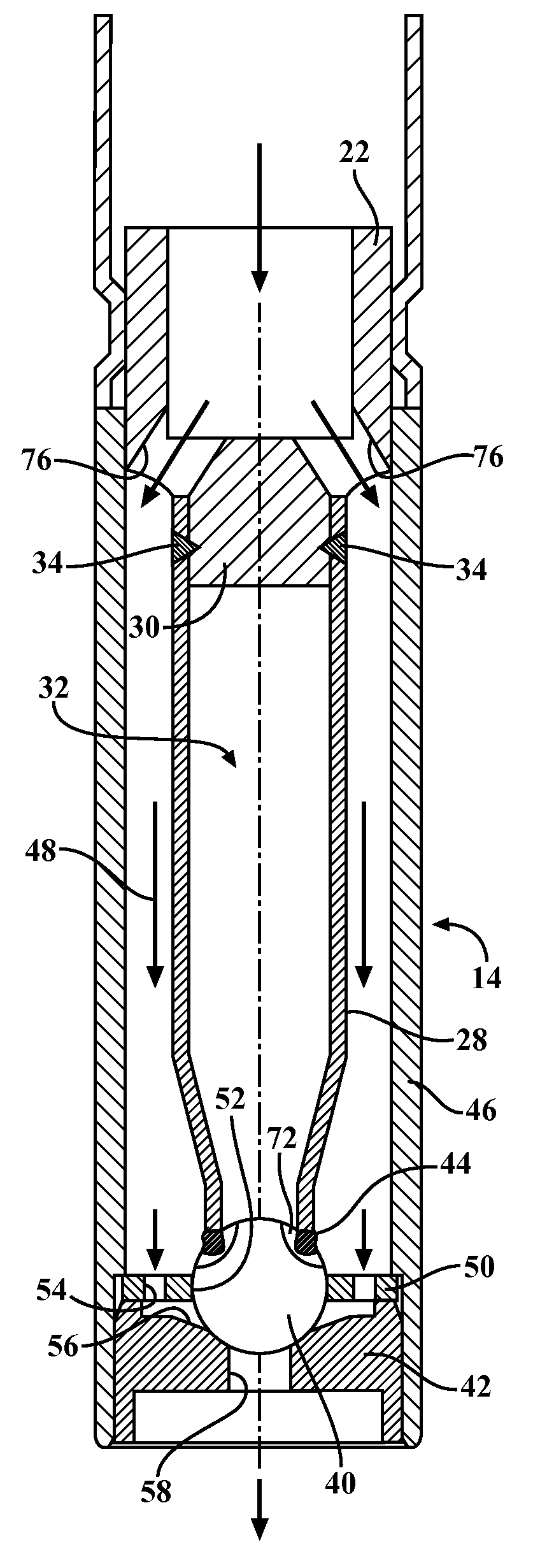
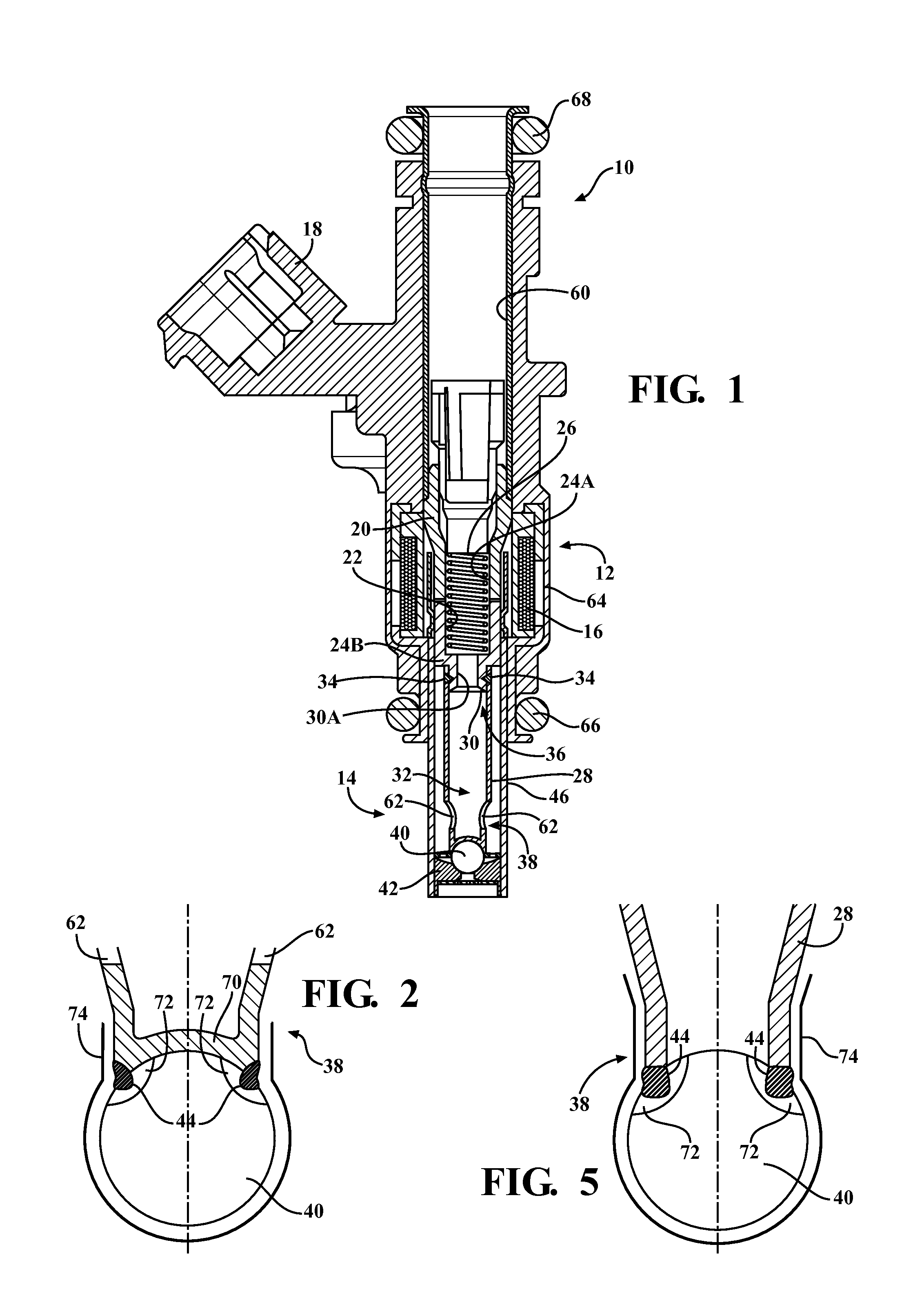
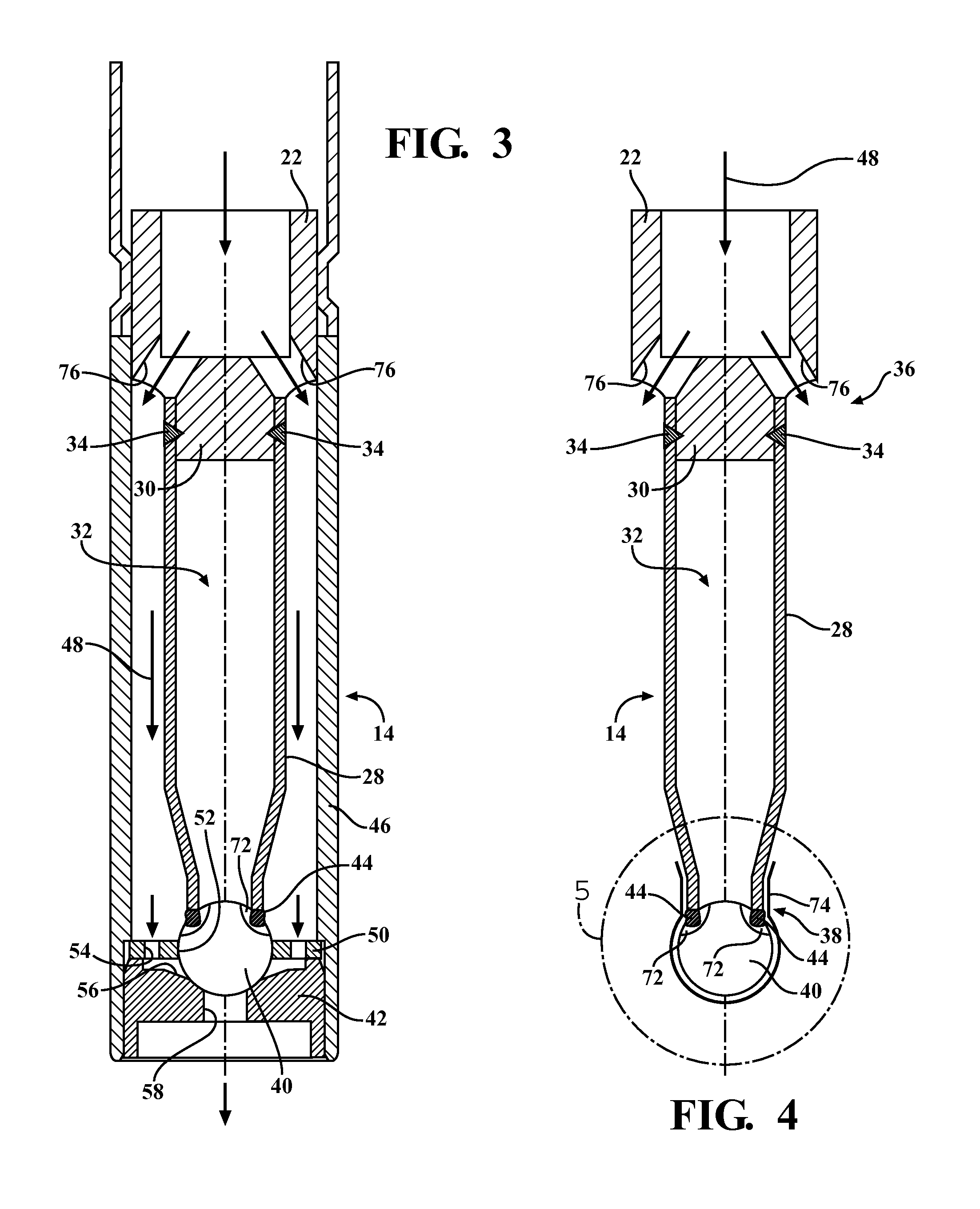
The present invention is an injector that prevents corrosion caused by diesel exhaust fluid. The injector has a tube connected to an armature with a small diameter portion. A weld connects the ball to the armature, and the ball is selectively in contact with a valve seat. The top of the ball is sealed from any exposure to the aqueous environment, mitigating the possibility of any corrosion. The injector has multiple upper exit apertures that allow diesel exhaust fluid to pass through the upper exit apertures and exit the valve portion. The use of a closed tube or sealed tube further prevents stagnant fluid areas and reduces the surface area exposed to DEF. In addition, the sealed tube reduces the moving mass and simplifies the manufacturing process.

Problems solved by technology

It is known that stagnant fluid is detrimental to corrosion resistance.

Method used


Image

  • Sealed armature ball tube assembly
  • Sealed armature ball tube assembly
  • Sealed armature ball tube assembly

Examples


Embodiment Construction

[0021]The following description of the preferred embodiment(s) is merely exemplary in nature and is in no way intended to limit the invention, its application, or uses.

[0022]A fuel injector according to embodiments of the present invention is shown generally at 10. The injector 10 includes a solenoid portion, shown generally at 12, and a valve portion, shown generally at 14. The solenoid portion 12 includes a solenoid having a coil 16 which is in electrical communication with a connector 18. The coil 16 at least partially surrounds a pole piece 20, and also at least partially surrounds an armature 22. The armature 22 is moveable relative to the pole piece 20, and both the pole piece 20 and armature 22 each have a cavity 24A and 24B respectively. Partially disposed in each of the cavities 24A,24B is a spring 26, which biases the armature 22 away from the pole piece 20, and the valve portion 14 toward a closed position.

[0023]The valve portion 14 includes a tube 28 connected to the arm...


PUM


Abstract

An injector having a tube attached to an armature. The injector includes a solenoid portion and a valve portion controlled by the solenoid portion. The armature includes a small diameter portion. Also included is a tube having a cavity, a first end of the tube is connected to the small diameter portion, and a ball is connected to a second end of the tube, such that the ball is selectively in contact with a valve seat. A hermetic weld connects the ball to the second end, and at least one heat affected zone is located in proximity to the hermetic weld. A coating substantially surrounds the heat affected zone and at least a portion of the ball, such that the coating prevents the heat affected zone from being exposed to diesel exhaust fluid and thus subsequent corrosion.

Description

FIELD OF THE INVENTION[0001]The invention relates generally to injectors, and more specifically, a treated valve which reduces corrosion due to exposure to diesel exhaust fluid (DEF) and condensed diesel exhaust system gases.BACKGROUND OF THE INVENTION[0002]Injectors are a commonly used device for injecting fuel into the cylinders of an internal combustion engine, as well as injecting diesel exhaust fluid (DEF) into the exhaust flow path, more particularly the exhaust pipe. While DEF alone is not corrosive, DEF has the capacity to support a corrosion reaction due to its conductivity. DEF and condensed diesel exhaust system gases support electrochemical corrosion of stainless steel components within the injector.[0003]Some types of injectors have a ball which is part of a valve, and the ball selectively contacts a valve seat, depending upon whether or not the valve is opened or closed. The injector may include a solenoid portion which actuates the valve. Various parts of the injector...

Claims


Application Information

Patent Timeline
Patent Type & Authority Patents(United States)
IPC IPC(8): F02M55/02F02M61/18F16K31/06
CPCF16K31/0662F02M61/188F16K31/0651F02M2200/8084
Inventor MCFARLAND, ROBERT WAYNE
Owner VITESCO TECH USA LLC
Learn More