
Battery assisted RFID tag with square-law receiver and optional part time active behavior

Active Publication Date: 2016-06-14
ZEST LABS INC
View PDF68 Cites 16 Cited by
  • Summary
  • Abstract
  • Description
  • Claims
  • Application Information

AI Technical Summary

Benefits of technology

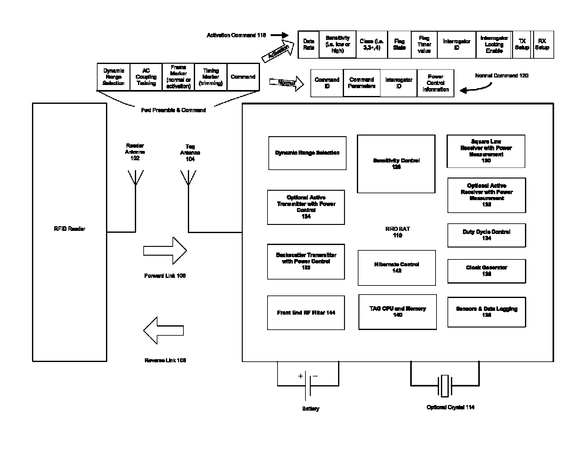
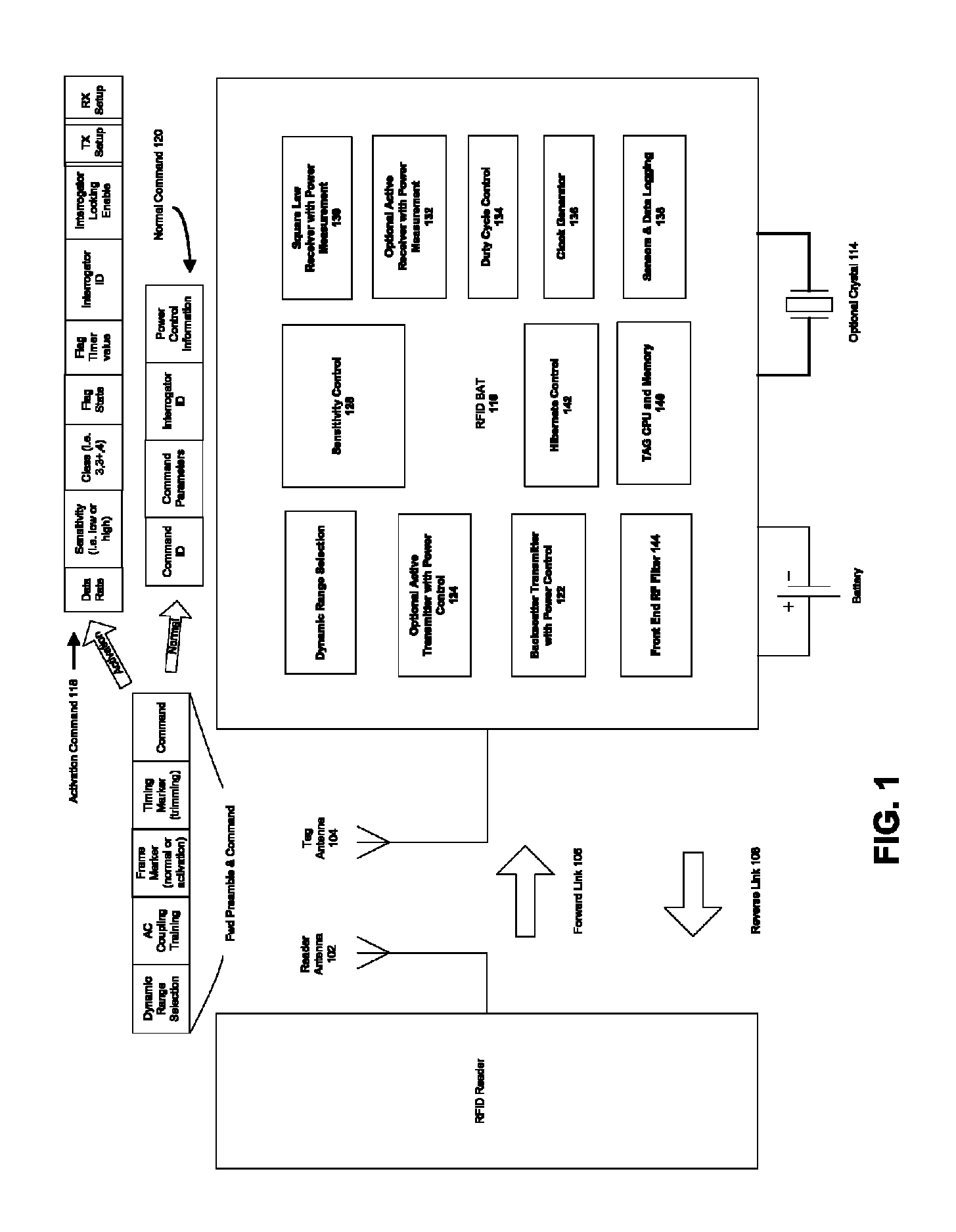
The patent is about a new type of battery-supported RFID system that can be used in various applications. The system has improved sensitivity and can communicate with both passive and fully-active RFID tags. It uses dynamic range states to cover the required tag receiver dynamic range and includes methods for training tag receivers, selecting the proper dynamic range state, and AC coupling training and symbol and frame synchronization. The system also has improved interference control to protect the sensitivity of readers and tags. The patent offers a scalable system design for various performance and price tags, allowing users to select the tag performance needed under a common system and infrastructure design. Overall, the patent provides a more efficient and flexible RFID infrastructure for various applications.

Problems solved by technology

These system generally operate from ranges of a few centimeters to approximately 1 meter, and are limited in range due to the physics of “near field” communications that do not rely on a propagating electromagnetic wave.
Because these tags are effectively powered by the field of an RFID reader, the distance the tag can communicate is limited by its own power consumption.
These active systems can achieve ranges of hundreds of meters, but cost significantly more than passive systems.
Additionally, the operational life of the active systems is limited by the batteries deployed within the tags and the ability to replace these batteries over the life of the system.
Some applications, such as tracking of military supplies, can absorb the relatively higher cost of these active systems, but many others cannot.

Method used


Image

  • Battery assisted RFID tag with square-law receiver and optional part time active behavior
  • Battery assisted RFID tag with square-law receiver and optional part time active behavior
  • Battery assisted RFID tag with square-law receiver and optional part time active behavior

Examples


case 2

2. ACCIDENTAL WAKE-UP WHEN TOGGLING ON NOISE

[0332]By inspection,

[0333]RAon=(FlagRate)⁢(Random⁢⁢Flag⁢⁢Probability)=DRNflag⁢2-2⁢⁢Nflag=DRNflag⁢22⁢⁢NflagEquation⁢⁢49

[0334]Note that because Nflag is in NRZ format, there are two trials per NRZ bit to get a random matching Manchester bit, hence the factor of 2 on Nflag.

[0335]Substituting this relation into the basic equation for Fw (Equation 43):

[0336]Fw=Ion⁢TAon⁢RAonIhib=IonIhib⁢BD⁢⁢FDR⁢DRNflag⁢22⁢⁢Nflag=IonIhib⁢BD⁢⁢FNflag⁢22⁢NflagEquation⁢⁢50

[0337]This equation may be rearranged as an inequality to use as an indicator of acceptable length for Nflag for negligible false wake-ups. When the below inequality exceeds 1.0, then the flag is of acceptable length.

[0338]Nflag⁢22⁢⁢Nflag⁢Ihib⁢FwIon⁢BD⁢⁢F=B⁢⁢L⁢⁢A⁢⁢F≥1Equation⁢⁢51

[0339]Now we may examine a particular cases of a high sensitivity receivers of −55 dBm with hibernate currents of 2 μA. Parameters assumed are:[0340]Ihib=2 μA (case 1) and 100 nA (case 2)[0341]Fw=0.01 (1% reduction in batte...


PUM


Abstract

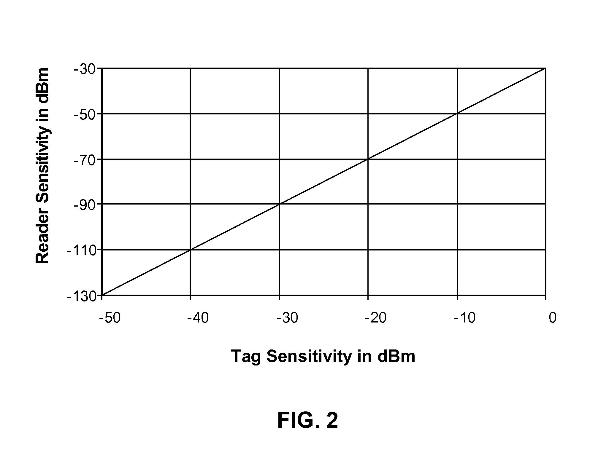
Embodiments of the present invention provide RFID systems having battery-assisted, Semi-Passive RFID tags that operate with sensitive transistor based square law tag receivers utilizing a plurality of tag receiver dynamic range states. Embodiments of the present invention are also enhanced with receiver training and synchronizing methods suited to the high tag sensitivity and need for dynamic range state switching. These enhancements may employ pseudo-random sequence based receiver training, activation signaling, and frame synchronizing. Further enhancement is achieved via design of system command sets and tag state machine behavior that control system interference and allow maximum usage of high sensitivity. Command set design also allows for convenient expansion to active transmitters and receivers in tags operating within the same system. Additional enhancement attained via power leveling methods that optimize the amount of transmitted power and interference from a reader in relation to the sensitivity of the RFID tags, their ranges from the reader, and the unique physics of the backscatter RFID radio link.

Description

BACKGROUND[0001]A. Field of the Invention[0002]The present invention relates generally to the field of Radio Frequency Identification (hereinafter, “RFID”) systems, and more particularly to advanced RFID systems which employ battery supported RFID tags allowing a higher degree of active behavior in tags.[0003]B. Background of the Invention[0004]The applications and importance of RFID technology has significantly grown in recent years due to a number of reasons including improvements in IC processes, RFID standards development, government allocation of increased spectrum for RFID, and growing awareness of the value of automated tracking of assets. During this growth, RFID systems have progressed from relatively simple, lower-frequency systems to include more complex systems that operate in the longer-range Ultra-High Frequency spectrum. The lower-frequency, generally inductively-coupled systems are usually referred to as Low Frequency (hereinafter “LF”, approximately 100-150 KHz) and...

Claims


Application Information

Patent Timeline
IPC IPC(8): H04Q5/22G06K7/00G06K19/077
CPCG06K7/0008G06K19/07749G06K19/0702
Inventor DACUS, FARRONBOUCHEZ, JOSEPHVAN NIEKERK, JOHANNES ALBERTUSRODRIGUEZ, ALFONSO
Owner ZEST LABS INC
Learn More