
Plasma processing apparatus and high frequency generator

a technology of plasma processing apparatus and generator, which is applied in the direction of electrical apparatus, plasma technique, electric discharge tubes, etc., can solve the problems of unstable and uniform plasma generation, unsatisfactory machine difference, and inability to obtain ideal waveform, etc., to achieve wide process conditions, suppress the influence of machine difference on the process, and generate more stably

Active Publication Date: 2016-06-21
TOKYO ELECTRON LTD
View PDF12 Cites 1 Cited by
  • Summary
  • Abstract
  • Description
  • Claims
  • Application Information

AI Technical Summary

Benefits of technology

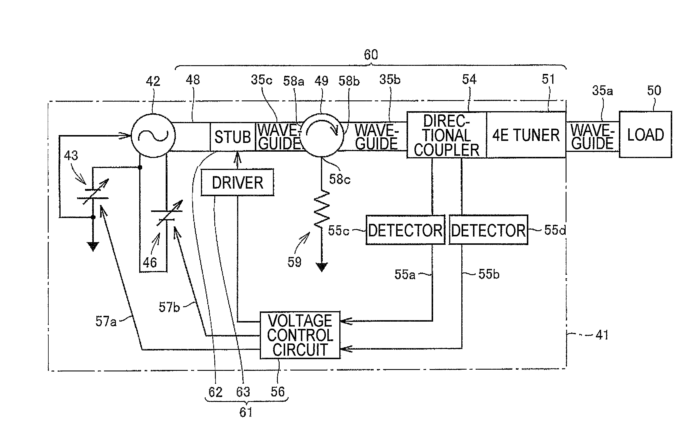
The plasma processing apparatus described in this patent allows for the voltage standing waves in the waveguide path to be adjusted based on the power supplied from the power supply unit. This can lead to a steep peak and a narrow skirt region in the fundamental frequency waveform, even with low power. This results in stable and uniform plasma in the processing container, regardless of any position differences in the peak. This allows for a wider range of process conditions and ensures a stable plasma generation over a broad range of power settings.

Problems solved by technology

When the value of power set for generating microwaves is reduced, the machine difference is likely to appear remarkably among the magnetrons and an ideal waveform may not be obtained.
Consequently, stable and uniform plasma may not be generated which may affect a plasma processing performed on a processing target substrate.

Method used


Image

  • Plasma processing apparatus and high frequency generator
  • Plasma processing apparatus and high frequency generator
  • Plasma processing apparatus and high frequency generator

Examples


Embodiment Construction

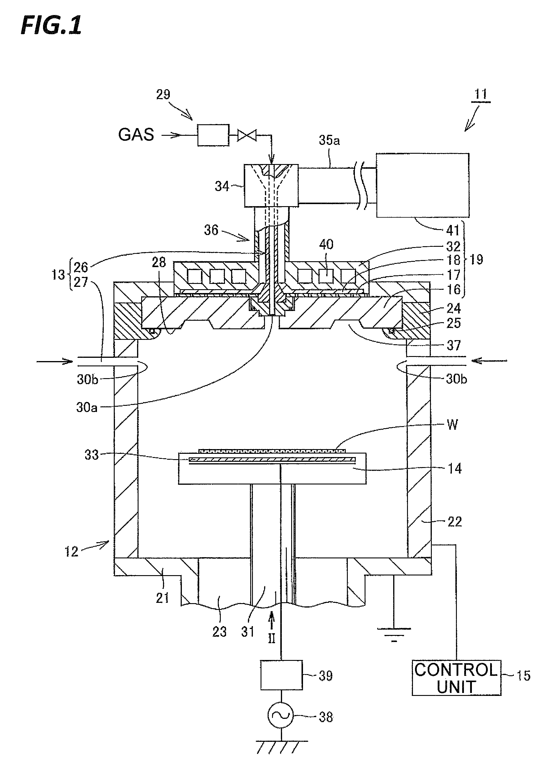
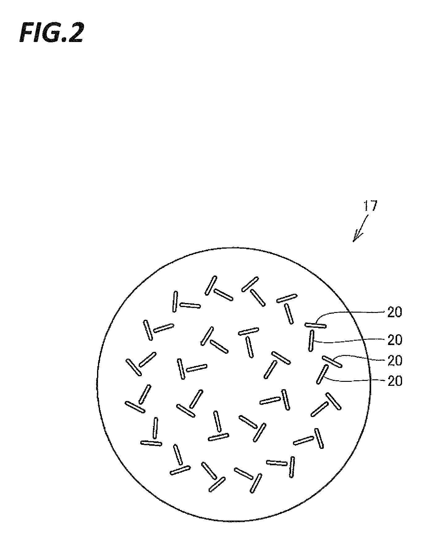
[0057]Hereinafter, exemplary embodiments of the present invention will be described with reference to the accompanying drawings. FIG. 1 is a schematic cross-sectional view illustrating main parts of a plasma processing apparatus according to an exemplary embodiment of the present invention. FIG. 2 is a view illustrating a slot antenna plate included in the plasma processing apparatus illustrated, in which the slot antenna plate is viewed from the bottom side, i.e. in the direction indicated by arrow II in FIG. 1. In FIG. 1, hatching is omitted for some components for easy understanding. In the present exemplary embodiment, the upward and downward direction in FIG. 1, which is indicated by the direction indicated by arrow II or the reverse direction, is assumed as the vertical direction in the plasma processing apparatus.

[0058]Referring to FIGS. 1 and 2, the plasma processing apparatus 11 performs a processing using plasma on a processing target substrate W which is an object to be p...


PUM


Abstract

Provided is a plasma processing apparatus that performs a processing on a processing target object using plasma. The plasma processing apparatus includes a processing container and a plasma generating mechanism including a high frequency generator disposed outside of the processing container to generate high frequency waves. The plasma generating mechanism generates plasma in the processing container using the high frequency waves and includes: a high frequency oscillator that oscillates the high frequency waves; a power supply unit that supplies a power to the high frequency oscillator; a waveguide path that propagates the high frequency waves oscillated by the high frequency oscillator to the processing container side which becomes a load side; and a voltage standing wave ratio variable mechanism that varies a voltage standing wave ratio of voltage standing waves formed in the waveguide path by the high frequency waves, according to the power supplied from the power supply unit.

Description

CROSS REFERENCE TO RELATED APPLICATION[0001]This application is a 35 U.S.C. 371 National Phase Entry Application from PCT / JP2013 / 064876, filed May 29, 2013, which claims priority to Japanese Patent Application No. 2012-176668, filed Aug. 9, 2012, the disclosures of which are incorporated herein in their entirety by reference.TECHNICAL FIELD[0002]The present invention relates to a plasma processing apparatus and a high frequency generator. In particular, the present invention relates to a high frequency generator that generates microwaves, and a plasma processing apparatus that generates plasma using the microwaves.BACKGROUND[0003]Semiconductor elements such as, for example, a large scale integrated circuit (LSI), a metal oxide semiconductor (MOS) transistor, a liquid crystal display (LCD), and an electro luminescence (EL) element, are manufactured by performing a processing such as, for example, etching, chemical vapor deposition (CVD), or sputtering, on a processing target substrat...

Claims


Application Information

Patent Timeline
Patent Type & Authority Patents(United States)
IPC IPC(8): H01J37/32H05H1/46
CPCH05H1/46H01J37/32192H01J37/32229H01J37/32256H01J37/3211H01J37/32119H01J37/32128H05H2001/4622H01J2237/327H01J2237/3321H01J2237/334H05H1/4622H01J37/3222H01J37/32311
Inventor KANEKO, KAZUSHIFUNAZAKI, KAZUNORIKATO, HIDEO
Owner TOKYO ELECTRON LTD
Learn More