Flow control valve

a flow control and valve device technology, applied in the direction of fluid pressure control, pressure relieving devices on sealing faces, instruments, etc., can solve the problems of large volume flow control, high energy demand, and large volume of the valve device, and achieve precise volume flow control, small overall size, and minimize energy demand

Active Publication Date: 2016-07-19
HYDAC FLUITECHNIK GMBH
View PDF11 Cites 1 Cited by
  • Summary
  • Abstract
  • Description
  • Claims
  • Application Information

AI Technical Summary

Benefits of technology

[0008]An object of the present invention is to provide an improved electromagnetic proportional flow control valve that permits a small overall size and at the same time a precise volume flow control over the entire anticipated operating range, and that minimizes energy demand.
[0009]Such an object is basically achieved by a flow control valve having a pressure detecting piston that serves for the action of the actuator part on the control piston. The fluid inlet is connected in a fluid-conducting manner to a pressure detecting chamber by a pressure detecting duct such that the fluid pressure prevailing in the pressure detecting chamber applies a force to the pressure detecting piston and the control piston in the direction of a relief of the actuator. The pressure detecting piston is loosely connected to the control piston. As a result, forces act on the pressure detecting piston in the direction of a relief of the proportional solenoid. In addition, the necessary actuating forces for the control piston are reduced in that its projection surface is decreased in the fluid flow direction by the cross-sectional area of the pressure detecting piston that extends, as required, into the control piston. As a result, the flow control valve according to the present invention has two design measures in the smallest space to reduce the necessary actuating forces and, thus, the energy consumption for its valve element in the form of the control piston, that is, by the reverse action of the fluid flow on the pressure detecting piston through the application of fluid to the rear side of the pressure detecting piston in the pressure detecting chamber and the associated reduction of the influent flow and / or pressurized projection surface or end face of the control piston itself. In total, the result is a reduction in the resulting overall pressure-effective surface. Thus, in total, the result is an electromagnetically operable flow control valve, which has markedly flat characteristic curves, so that the solenoid drive force of the flow control valve is evened out in relation to an identical actuating current over the entire range of the valve stroke, as a result achieving characteristic curves that are almost 100% linear is possible.
[0010]The control surfaces of the control piston and the pressure detecting piston, to which pistons fluid pressure is effectively applied, and when subtracted from each other, a remaining control surface, to which fluid pressure is applied, introduces a force to the two pistons in such a way that the result is a relief for the proportional solenoid. Without the pressure detecting piston with its pressure-effective detecting piston rear side, all of the fluid pressure on the fluid inlet side of the valve would be available on the facing front side of the valve element or the control piston, with the result that the proportional solenoid would have to generate very high actuating forces for the valve element, and respectively the control piston. This state in turn would assume that the proportional solenoids inside the valve device were large in size and also had a correspondingly high energy demand. The use of the pressure detecting piston serves to reduce, as explained, the necessary actuating forces, so that proportional solenoids that are small in size suffice for the actuating functions with a correspondingly low power demand. Moreover, the pressure detecting piston also supports the modular design of the flow valve, because the valve components, including the proportional solenoid, can be installed in standardized size gradations to be able to cover a wide range of performance classes of the fluid flows to be controlled. Surprisingly to the average person skilled in the field of valve engineering, for the first time the actuating force of the proportional solenoid can be reduced through the use of a pressure detecting piston and a fluid guide on its side facing the proportional solenoid.
[0017]The diameter of the pressure detecting piston or its cross-sectional area is the smallest in the area of the metering orifice of the control piston. The metering orifice can have about the same inside diameter as the largest diameter of the pressure detecting piston or can be slightly larger, so that during assembly the pressure detecting piston can be guided, for example, from the side of the metering orifice opening, through which the control piston can be guided. The pressure detecting piston can be loosely connected to the control piston by a drive plate and, in particular, to the effect that the drive plate can take with it the control piston in the active direction of the energized proportional solenoid coil. In any case, both pistons can move relative to each other in the opposite direction of movement of the armature and the pressure detecting piston. However, preferably, both of those pistons are operatively connected together with a small pretensioning force via the drive plate by a separate compression spring in any position of movement.

Problems solved by technology

This state in turn would assume that the proportional solenoids inside the valve device were large in size and also had a correspondingly high energy demand.

Method used


Image

  • Flow control valve
  • Flow control valve
  • Flow control valve

Examples


Embodiment Construction

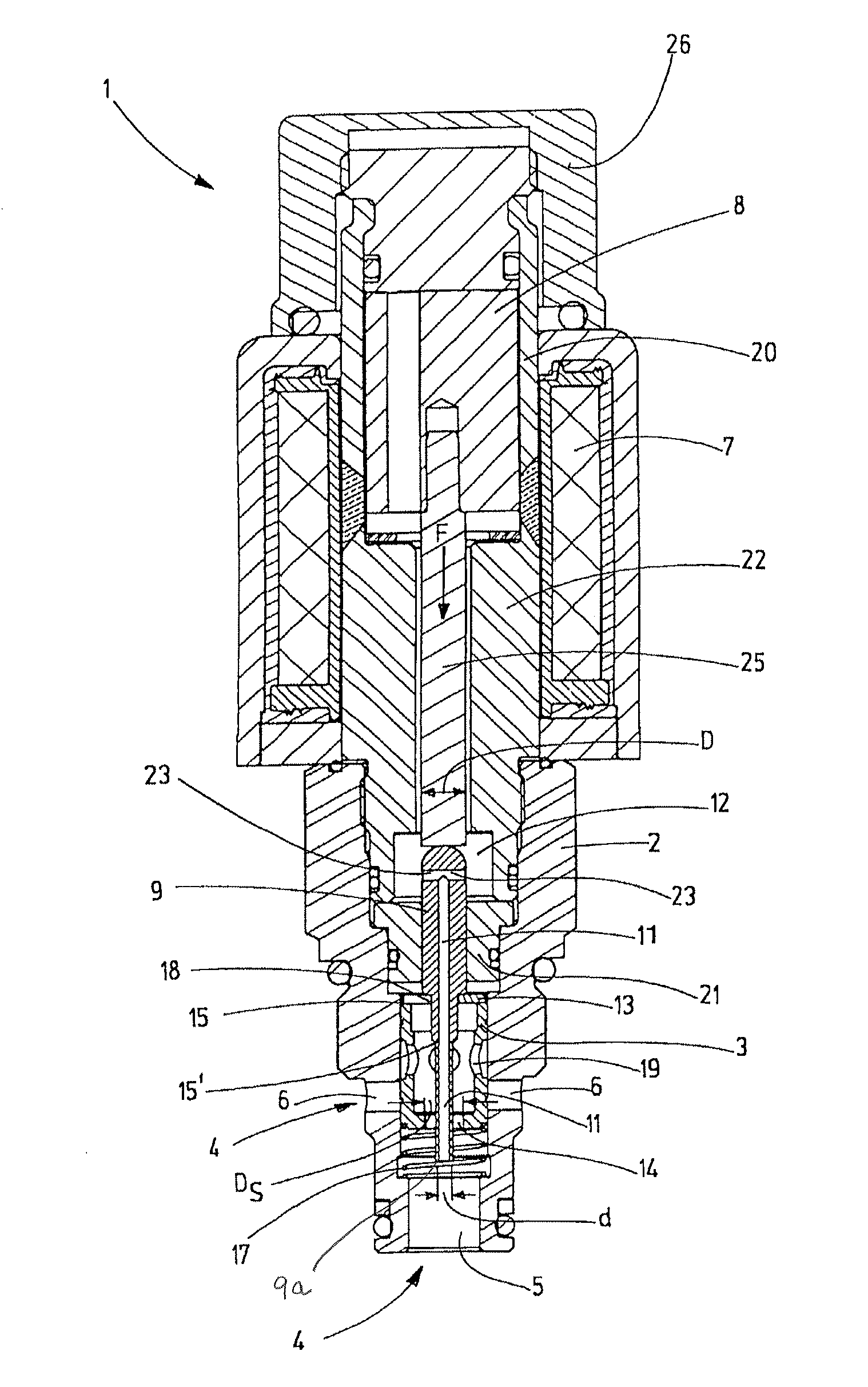
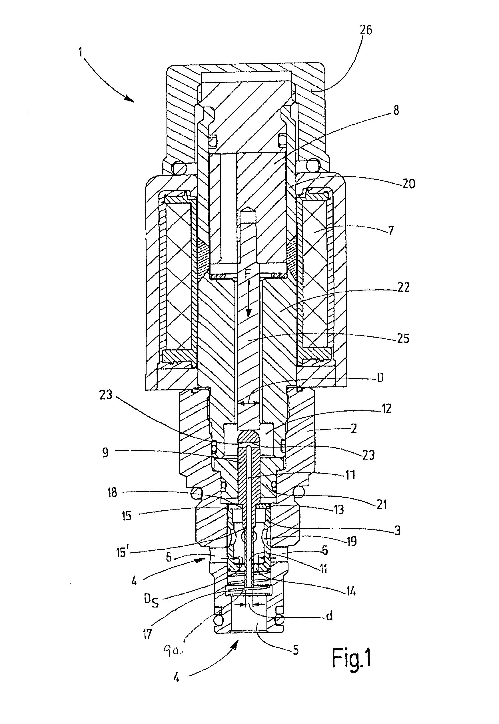
[0027]FIG. 1 is a longitudinal sectional view of an electromagnetic 2-way proportional flow control valve 1 capable of holding a hydraulic fluid volume flow from a hydraulic fluid pump (not illustrated) to a hydraulically connected consumer (not illustrated) more or less constant, independently of any pressure fluctuations that might occur. The electromagnetic 2-way flow control valve 1 can control the volume flow on the influent flow side or the return side of the hydraulic consumer (not illustrated), for example, in the form of a working cylinder of a construction machine or the like.

[0028]The valve, hereinafter referred to only as the flow control valve 1, has a valve housing 2 configured as a screw-in cartridge solution. The lower, axial end of the valve housing 2 has a central fluid inlet 5 and several radial outflow openings or outlet 6, of which two are shown in the longitudinal sectional view. A sleeve shaped control piston 3, designed as a sliding piston, is guided such tha...


PUM


Abstract

An electromagnetic proportional 2-way flow control valve (1) has a valve housing (2) in which a control piston (3) is guided to be displaced axially. The control piston (3) actuates at least one fluid-conducting connection (4) between a fluid inlet (5) and an outflow opening (6). An armature (8) can be actuated by a proportional magnet and acts on the control piston (3). A pressure detecting piston (9) serves as the actuator part on the control piston (3). The fluid inlet (5) is connected in a fluid-conducting manner by a pressure detecting channel (11) to a pressure detecting chamber (12) such that the fluid pressure prevailing in the pressure detecting chamber (12) loads the pressure detecting piston (9) and the control piston (3) with a force (F) in the direction of relief of the armature.

Description

FIELD OF THE INVENTION[0001]The invention relates to a flow control valve, in particular in the form of an electromagnetic 2-way proportional flow control valve, having a valve housing, in which a control piston is guided to be displaced axially. The control piston actuates at least one fluid-conducting connection between a fluid inlet and an outflow opening. An actuator part, in particular an armature, which can be actuated by an actuator, in particular in the form of a proportional solenoid, acts on the control piston.BACKGROUND OF THE INVENTION[0002]Flow control valves, in particular a 2-way flow control valve, have the function of setting the volume flow to a constant value independently of the pressure differential and the viscosity of a fluid. Depending on the design of the respective flow control valve, the volume flow can be controlled on the influent flow side or the return side of a connected hydraulic consumer. Flow control valves with adjustable volume flow can be implem...

Claims


Application Information

Patent Timeline
Patent Type & Authority Patents(United States)
IPC IPC(8): F16K31/06F15B13/04B60T8/36F15B13/044G05D7/06F16K39/04
CPCF16K31/0675B60T8/3665F15B13/0402F15B13/0442F16K31/06F16K31/0668F16K39/04G05D7/0635Y10T137/7761Y10T137/86879Y10T137/8778G05D16/2024
Inventor WARD, CHRISTOPHERMALONE, PETER
Owner HYDAC FLUITECHNIK GMBH
Why Eureka
Try Eureka